1. Introduction#
The MCS500 is a four-axis industrial robot arm of type SCARA that is easy to use, robust, and lightweight. However, the robot is a precision device with rapidly moving parts and should therefore be used only by trained technical personnel who have read and understood this user manual, to avoid damages to the robot, its end-effector, the workpiece and adjacent equipment, and, most importantly, to avoid injuries.
Following the guidelines in this manual is essential to avoid damage to the robot, its end-effector, any workpiece and adjacent equipment, and most importantly, to prevent injuries to personnel. This manual will guide you through proper setup, operation, and maintenance procedures to ensure safe and effective use of your MCS500 robot.
1.1. Inside the box#
Table 1 lists the items that come with a standard shipment of an MCS500 robot system.
Warning
DO NOT remove the contents of the box until you read Section 2.
Qty |
SKU |
Description |
Photo |
|---|---|---|---|
1 |
9101-002
OR
9101-003
|
MCS500-R1, SCARA robot arm
OR
MCS500-R1-HS, SCARA robot arm with hollow spline shaft
|
|
1 |
9200-002 |
MSIPS-R1 module |
|
1 |
9403-003 |
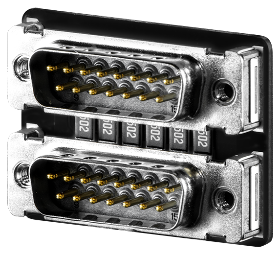
Dual D-Sub DB15 dongle |
|
1 |
2003-005 |
2-meter, M12 D-Code to RJ45, Ethernet cable |

|
1 |
2003-008 |
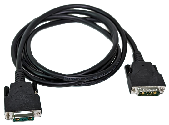
2-meter proprietary communications and DC power cable for MCS500 |
|
Note
You are responsible for supplying the following components:
An AC power cord with a three-prong IEC C13 connector on one end and a country-specific power plug on the other, along with a surge protector.
M6 screws of appropriate length for securing the robot’s base and MSIPS module.
Two cables with DB15 connectors.
A three-position enabling device.
Properly wired safety I/O connections.
Note
Do not discard your shipping box and packing foam.
1.2. Overall description#
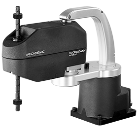
The MCS500 is a four-axis SCARA robot consisting of four actuated joints, numbered as shown in the figure below. Joint 1 is between the base and the proximal link and joint 2 is between the proximal link and the distal link. Finally, two motors work in tandem to control the translational and rotational movements of the spline shaft with respect to the distal link. The translational motion is referred to as joint 3, while the rotational motion as joint 4. The axes of joints 1, 2, and 4 are parallel to the direction of joint 3.
A retaining ring is mounted on both sides of the spline shaft. The two retaining rings are used for mounting tools but also for retaining the spline shaft. Never remove these rings or else you will permanently damage the spline shaft assembly.
In Figure 1, all joints are at their zero position. The figure also shows the positive directions of rotation or translation.
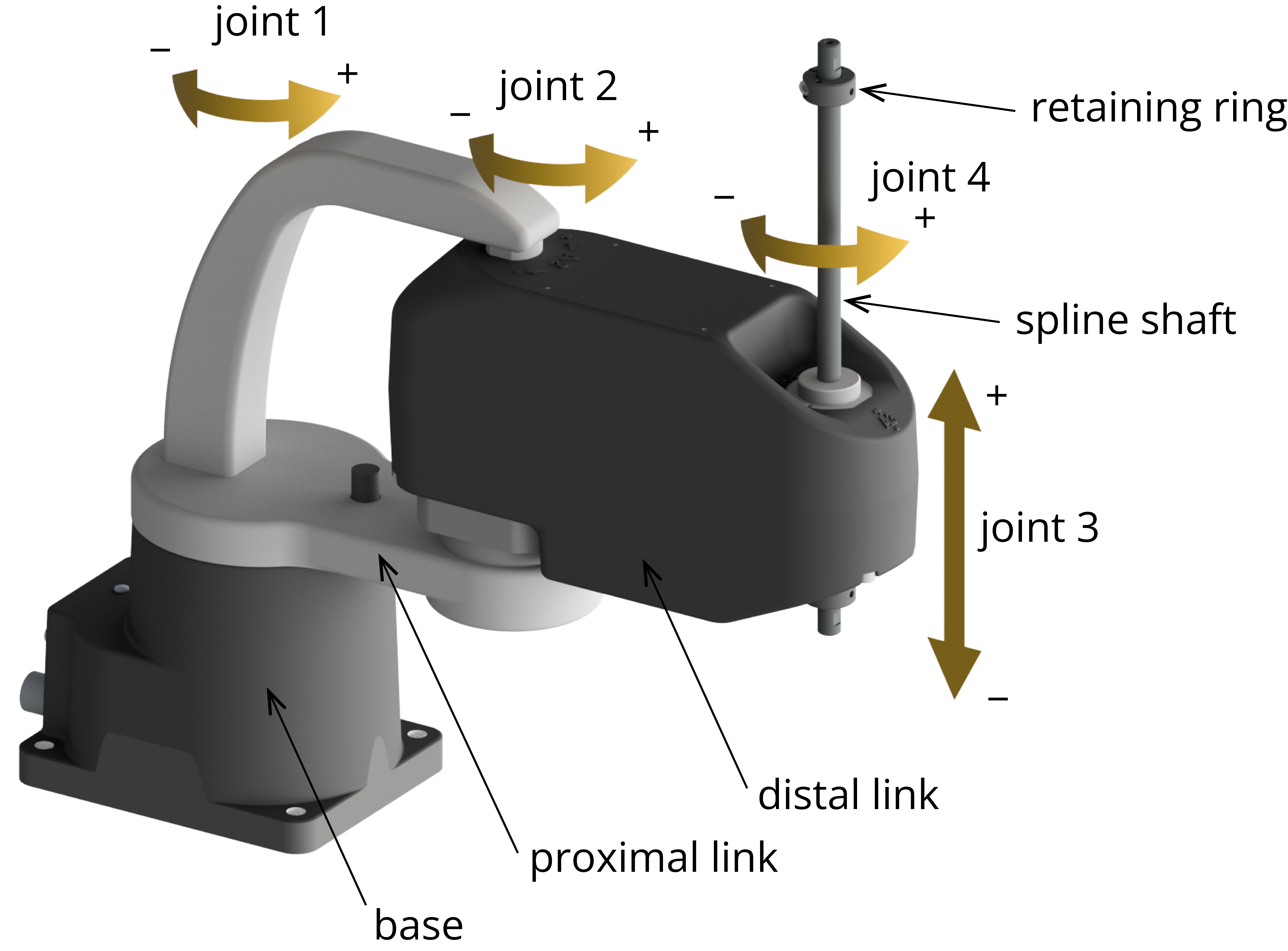
Figure 1 Joint numbering and nomenclature of the MCS500 SCARA robot#
The figure below shows a schematic of the complete MCS500 robot system in a typical installation. The dual DB15 dongle provided is not shown as it must be used only during setup and testing.


Figure 2 Schematic of the MCS500 robot system installed#
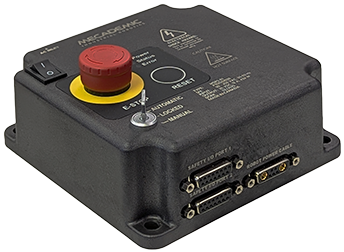
1.3. Description of the MSIPS module#
The MSIPS module, which includes the AC-DC power adapter, must be connected to an AC source supplying 90–250 V at 50–60 Hz, via a surge protector. Applying AC voltage outside this range may damage the MSIPS module.
Referring to the figure below, the main features of the MSIPS module are:
A: system on/off switch (“I” stands for ON, “O” stands for OFF);
B: emergency stop button (Stop Category 1), designed as PL=d with a Category 3 safety architecture, MUST BE PROPERLY WIRED IN ORDER TO FUNCTION;
C: indicator LEDs;
D: reset button;
E: operating mode key switch;
F, G: D-Sub DB15 interface for connecting safety I/Os to the robot;
H: connector for robot communications and DC power cable.


Figure 3 Description of the MSIPS module#
The following illustration shows the AC power connector, of type IEC C14, and indicates the Neutral (N), Protective Earth (PE) and Live (L) pins.


Figure 4 IEC C14 power entry receptacle on MSIPS module#
Use only the supplied, custom-made, communications and DC power cable to connect the robot to the MSIPS module and never modify this cable. Once the robot is connected to the MSIPS module and the module is plugged into a suitable AC source, you may switch on the MSIPS module.
When disconnecting the AC power, either by using the on/off switch on the MSIPS module or by unplugging the AC cord, the brakes on the last two motors will engage immediately, immobilizing the spline shaft. Therefore, to avoid premature wear of the brakes, NEVER disconnect the AC power when the robot is moving.
When disconnecting the AC power, activating the E-Stop function or activating the protective stop 1, joints 1 and 2 of the robot become free. This minimizes the risks of pinning and pinching from the robot.
The MSIPS module is equipped with
one E-Stop Button, which must be properly wired in order to function,
one Reset button,
one input connection for an external Reset,
safety (redundant) input connections for
one E-Stop function (Stop Category 1),
one external protective stop (Stop Category 1) that will be referred to as P-Stop 1,
one external protective stop (Stop Category 2) that will be referred to as P-Stop 2,
one external three-position enabling device,
and output connections for
one safety (redundant) Power Status signal,
one Reset Ready signal.
In order to be able to use the MCS500, you must properly connect your safety inputs on the D-Sub 15-position interface, as described in Section 2.3.2 or temporarily connect the dual DB15 dongle (not possible with the PS200NB).
1.4. Applied standards#
The MCS500 and its MSIPS module comply with the following European directives and harmonized standards:
Machinery directive 2006/42/EC
EN EIC 61326-1:2021 (Electrical equipment for measurement, control and laboratory use – EMC requirements – Part 1: General requirements)
EMC directive 2014/30/EU
Low voltage directive 2014/35/EU
RoHS Directive (EU) 2015/863
Harmonic Current Emission Limits EN IEC 61000-3-2 (2019) A1 (2021)
Voltage Fluctuations and Flicker Limitations EN 61000-3-3 (2013) A1 (2019) A2 (2021)
Electrostatic Discharge Immunity IEC 61000-4-2 (2008)
Radiated Electromagnetic Field Immunity IEC 61000-4-3 (2020)
Electrical Fast Transient Immunity IEC 61000-4-4 (2012)
Surge Immunity IEC 61000-4-5 (2014) A1 (2017)
Immunity to Conducted Disturbances, Induced by Radio-Frequency Fields IEC 61000-4-6 (2013)
Power Frequency Magnetic Field Immunity IEC 61000-4-8 (2009)
Further details related to EMC are given in Appendix 1.
In addition, the design of the MCS500 robot arm and its MSIPS module was guided by the following harmonized standards, incorporating a tailored approach to meet our unique objectives:
ISO 10218-1:2011 (Robots and robotic devices – Safety requirements for industrial robots. Part 1: Robots)
IEC 60204-1:2016 (Safety of machinery – Electrical equipment of machines. Part 1: General requirements)
ISO 13849-1:2015 and ISO 13849-2:2012 (Safety of machinery – Safety-related parts of control systems)
ISO 13850:2015 (Safety of machinery – Emergency stop – Principles for design)
The EU declaration of incorporation is provided in Appendix 3.

