1. Introduction#
The Meca500 is a six-axis industrial robot arm designed for moving tools and workpieces within factory or laboratory environments with high precision and six degrees of freedom. The Meca500 is easy to use, robust and lightweight. However, the robot is a precision device with rapidly moving parts and should therefore be used only by trained technical personnel who have read and understood this user manual.
Following the guidelines in this manual is essential to avoid damage to the robot, its end-effector, any workpiece and adjacent equipment, and most importantly, to prevent injuries to personnel. This manual will guide you through proper setup, operation, and maintenance procedures to ensure safe and effective use of your Meca500 robot.
1.1. Inside the box#
Table 1 shows the items that come with a standard shipment of a Meca500 robot system. Your box may also contain the MEGP 25E or MEGP 25LS electric gripper, the MPM500 pneumatic module, or other small accessories. Do not open these additional packages immediately. You must read the grippers (MC-UM-MEGP25) or pneumatic module (MC-UM-MPM500) user manuals prior to installing the end-of-arm tooling (EOAT) on the robot.
Warning
Do not remove the contents of the box until you read Section 2.
Qty |
SKU |
Description |
Photo |
|---|---|---|---|
1 |
9100-001
OR
9100-002
OR
9100-003
|
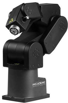
Meca500-R3 robot arm
OR
Meca500-R4 robot arm
OR
Meca500-R4-OB robot arm with optical black surface treatment
|
|
1 |
9200-001
OR
9200-003
OR
9200-004
|
PS200-R3 module
OR
PS200-R4 module
OR
PS200NB-R4 module without physical E‑Stop and Reset buttons
|
|
1 |
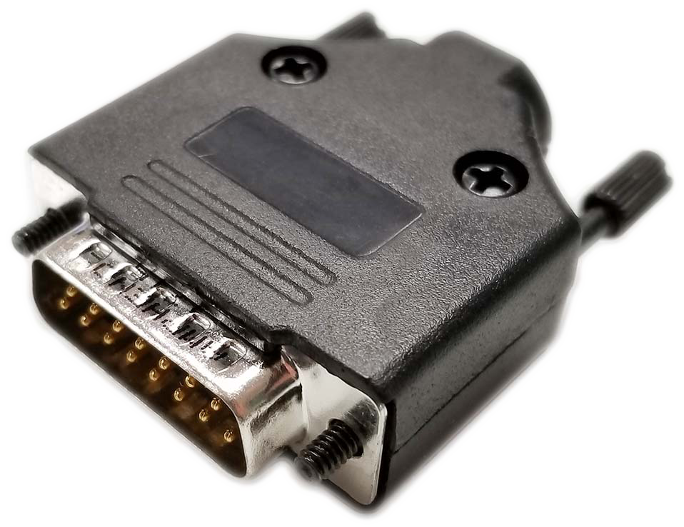
9403-001 |
D-Sub DB15 dongle (comes only with PS200-R3 and PS200-R4) |
|
1 |
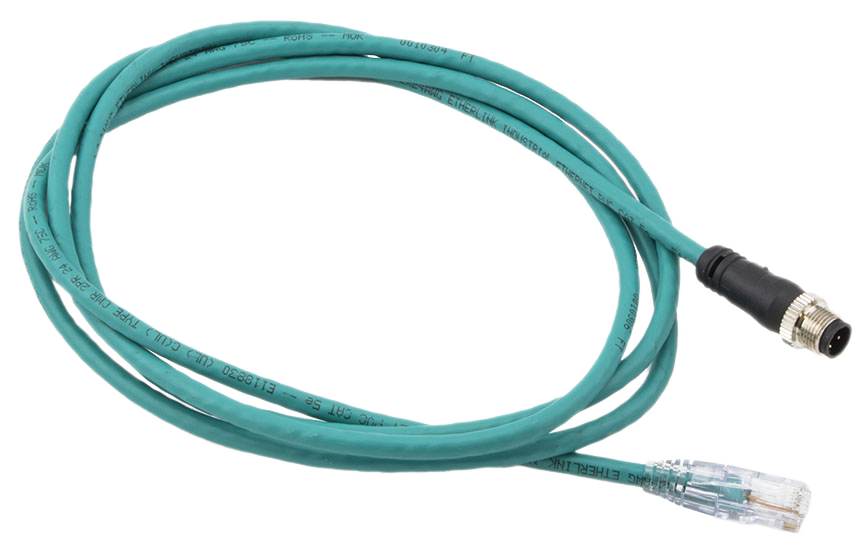
2003-005 |
2-meter, M12 D-Code to RJ45, Ethernet cable |
|
1 |
2003-006 |
2-meter, M12 circular male to M12 circular female, communications and DC power cable for Meca500 (R3 and R4) |

|
Note
You are responsible for supplying the following components:
An AC power cord with a three-prong IEC C13 connector on one end and a country-specific power plug on the other, along with a surge protector.
M6 screws of appropriate length for securing the robot’s base and PS200 module.
One cable with DB15 connector.
Properly wired safety I/O connections.
Note
Remember to not discard your shipping box and packing foam.
1.2. Overall description#
Figure 1 shows a schematics of the complete Meca500 robot system in a typical installation. The D-Sub 15-pin dongle provided is not shown as it must be used only during setup and testing. The Meca500 robot arm consists of seven bodies connected in series through six motorized revolute joints. The first body is the robot base and the seventh body is the flange (mechanical interface). The joints are numbered from 1 to 6 , starting from the joint connected to the base, and are labeled on the robot as A1, A2, …, A6. Joints 1, 2, and 3 are equipped with emergency brakes, which are automatically applied when power is removed from the motors. Joints 4, 5, and 6 have no brakes.


Figure 1 Schematic of the Meca500 robot system installed#
1.3. Description of the PS200 module#
The PS200 module, which includes the AC-DC power adapter, must be connected to an AC source supplying 90–250 V at 50–60 Hz, via a surge protector. Applying AC voltage outside this range may damage the PS200 module.
While the PS200 module includes the main power supply (AC to 24 V DC conversion), it also integrates safety I/O, an E-Stop and a Reset button, indicator LEDs, and internal logic. Use only the PS200 module provided by us to power your Meca500 robot arm. The Meca500 will not function with the PS200 module of another revision or with a third-party 24 V DC power supply.
Warning
The latest, R4, revision of the Meca500 incorporates one major change compared to version R3: the E‑Stop function no longer cuts power to the complete robot, but only to the motor drives. Do not use the PS200 module of an R3 version with a Meca500 R4, and vice versa. The R4 robot arms and PS200 modules are clearly indicated as being R4.
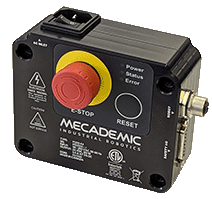
Figure 2 shows the standard PS200 module. Its main features are:
A: Emergency stop button (Stop Category 1), designed to achieve PL=d.
B: Power, Status and Error LEDs.
C: Reset button.
D: communications and DC power cable port (for connecting to robot).
E: D-Sub 15-position interface for connecting safety I/O.


Figure 2 Standard PS200 module#
Note
The optional PS200NB-R4 module is identical to the PS200-R4, except that it has no physical E‑Stop and Reset buttons.
Figure 3 shows the AC power connector, of type IEC C14, and indicates the Neutral (N), Protective Earth (PE) and Live (L) pins. It also illustrates the main switch (“I” stands for ON, “O” stands for OFF).


Figure 3 IEC C14 power entry receptacle and main switch#
Use only the supplied DC power cable to connect the robot to the PS200 module and never modify this cable. Once the robot is connected to the PS200 module and the module is plugged into a suitable AC source, you may switch on the PS200 module.
When disconnecting the AC power, either by using the on/off switch on the PS200 module or by unplugging the AC cord, the brakes on the first three joints will engage immediately. Therefore, to avoid premature wear of the brakes, never disconnect the AC power when the robot is moving.
When disconnecting the AC power, activating the E-Stop function or activating the protective stop 1, joints 3, 4 and 5 of the robot become free. This minimizes the risks of pinning and pinching from the robot.
The PS200 module is equipped with
one E-Stop button (Stop Category 1), designed to achieve PL=d,
one Reset button,
one input connection for an external Reset,
one external software stop that will be referred to as SWStop (not safety rated),
safety (redundant) input connections for
one E-Stop function (Stop Category 1),
one external protective stop (Stop Category 1) that will be referred to as P‑Stop 1,
and output connection for
one Power Status signal.
1.4. Applied standards#
The Meca500 R4 and its PS200 module comply with the following European directives and harmonized standards:
Machinery directive 2006/42/EC
EN EIC 61326-1:2021 (Electrical equipment for measurement, control and laboratory use – EMC requirements – Part 1: General requirements)
EMC directive 2014/30/EU
Low voltage directive 2014/35/EU
RoHS Directive (EU) 2015/863
Harmonic Current Emission Limits EN IEC 61000-3-2 (2019) A1 (2021)
Voltage Fluctuations and Flicker Limitations EN 61000-3-3 (2013) A1 (2019) A2 (2021)
Electrostatic Discharge Immunity IEC 61000-4-2 (2008)
Radiated Electromagnetic Field Immunity IEC 61000-4-3 (2020)
Electrical Fast Transient Immunity IEC 61000-4-4 (2012)
Surge Immunity IEC 61000-4-5 (2014) A1 (2017)
Immunity to Conducted Disturbances, Induced by Radio-Frequency Fields IEC 61000-4-6 (2013)
Power Frequency Magnetic Field Immunity IEC 61000-4-8 (2009)
Further details related to EMC are given in Appendix 1 and Appendix 2.
In addition, the design of the Meca500 R4 robot arm and its PS200 module was guided by the following harmonized standards, incorporating a tailored approach to meet our unique objectives:
ISO 10218-1:2011 (Robots and robotic devices – Safety requirements for industrial robots. Part 1: Robots)
IEC 60204-1:2016 (Safety of machinery – Electrical equipment of machines. Part 1: General requirements)
ISO 13849-1:2015 and ISO 13849-2:2012 (Safety of machinery – Safety-related parts of control systems)
ISO 13850:2015 (Safety of machinery – Emergency stop – Principles for design)
The EU Declaration of Incorporation (DOI) is available in Appendix 4.

