4. Installing the robot system#
It is imperative that you fix solidly the base of your robot arm with four M6
screws, tightened at 3 Nm, before activating the robot. We typically use metric
breadboards such as those from
Thorlabs, but you can
also use our adapter plate
(MUAP02.zip ), build your entire
robot cell at Vention, or use the modular system made by
Tessella Automation. We recommend that you use
three kinematic positioners against the vertical edges of your base to
constrain its position, ensuring it can be repeatedly removed and reinstalled in the
same location.
), build your entire
robot cell at Vention, or use the modular system made by
Tessella Automation. We recommend that you use
three kinematic positioners against the vertical edges of your base to
constrain its position, ensuring it can be repeatedly removed and reinstalled in the
same location.
The dimensions of the base are provided below, along with an example of an installation. Note that you can also install the robot base upside-down, and there is no setting to specify this orientation. Also, note that you can mount the robot’s base on a mobile body (e.g., on the carriage of a linear guide), but care must be taken to ensure that the combined acceleration of the robot and the linear guide won’t exceed the capacity of the robot in case an emergency deceleration is required.
Note
While the base of the MSC500 has the same bolt pattern as the base of the Meca500, it is slightly larger. Therefore, you cannot use our adapter plate for the Meca500 (MUAP01) unless you remove the locating pins. You should rather use our MUAP02 adapter plate, designed for the MCS500.
Warning
Ensure the mounting surface is perfectly flat, and that nothing presses on the underside cover of the robot base or contacts the exposed connectors.
Danger
Secure the robot base firmly using four M6 screws tightened to a torque of 3 Nm. Periodically inspect the screws to ensure they remain properly tightened.


Figure 15 Dimensions of the base of the MCS500#
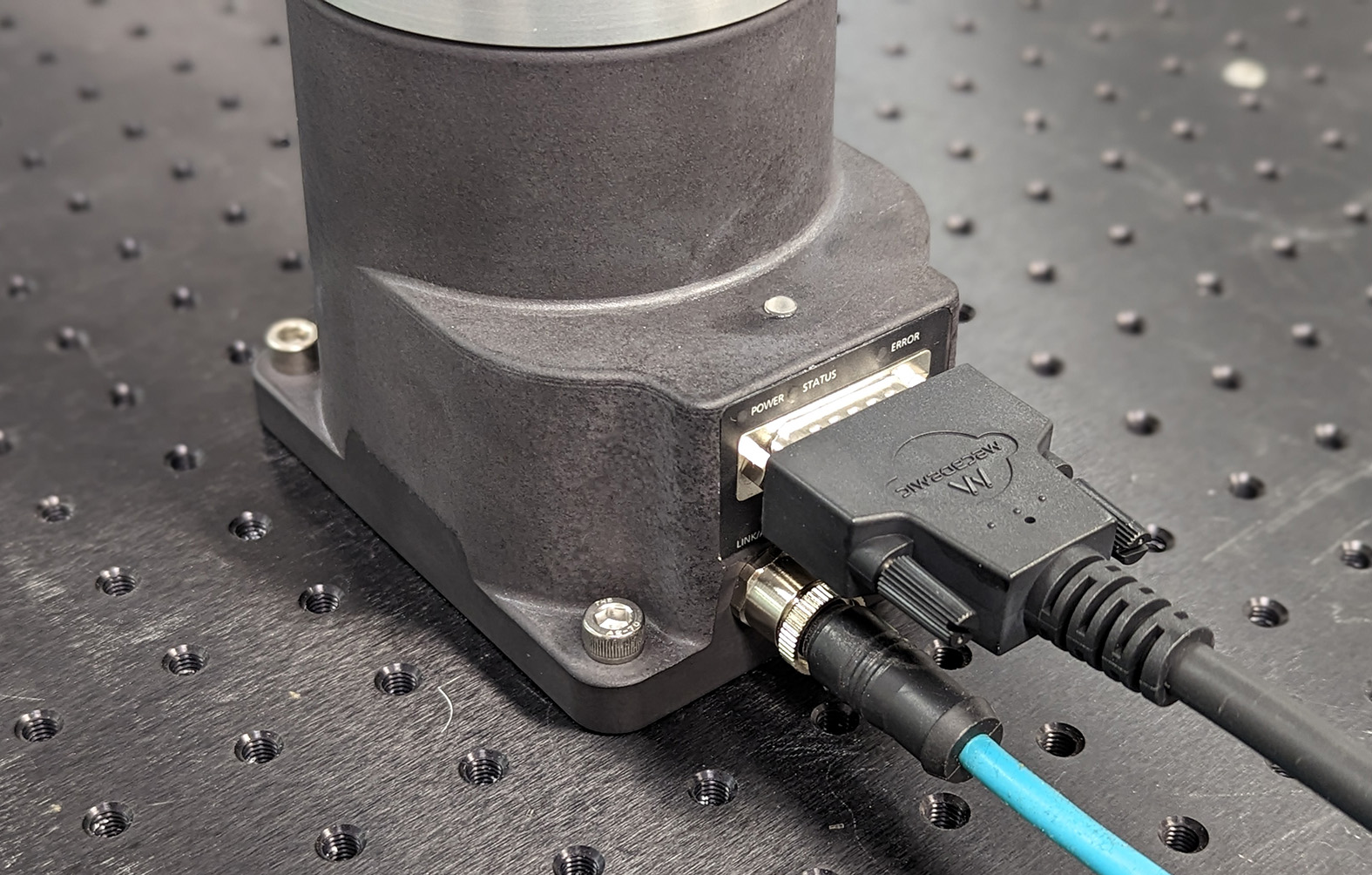
Figure 16 The robot base installed#
If you are using the MVK01 Vacuum and I/O module, refer to its user manual. The MVK01 module must be installed underneath the base of the MCS500.
Do not install any end-effector yet. We will cover this topic in Section 6.
Next, securely mount the MSIPS module using four M6 screws (see figure below), positioning it close enough to the robot base to accommodate the provided 2-meter DC cable. However, unless an external emergency stop is connected via the D-Sub connector, the MSIPS module must be mounted in a location where the internal E-Stop button remains easily accessible to the operator and outside the robot’s working range.
Warning
Mount the MSIPS module vertically. To improve heat dissipation, secure it to a solid metal plate.


Figure 17 Dimensions of the MSIPS module#
Next, attach the circular connector of the Ethernet cable to the ETHERNET1 port on the robot’s base and connect the RJ-45 jack to your computer or router (see the figure Figure 16). The two Ethernet ports on the robot base act as a bridge, so you can daisy-chain several MCS500 robots, or connect an Ethernet I/O module on the ETHERNET2 port.
Finally, use the DC power cable provided to connect the unpowered MSIPS module to the robot’s DC power connector (see the figure Figure 16). Make sure the connectors are completely screwed, or else you may damage the robot. Then, connect the MSIPS module to your country-specific AC power cord (not provided).
Warning
Always connect the DC power cable before connecting the MSIPS module to an AC outlet. Always disconnect the MSIPS module from the AC outlet before disconnecting the DC power cable.