2. Safety#
The Meca500 weighs less than 5 kg, however, it can move fast and cause injuries, especially when certain end-effectors are attached to its flange (e.g., a sharp tool or a laser).
Note
We designed this robot with the principles of ISO 10218-1 in mind. However, the robot is not fully compliant with this standard and has not been certified by an independent third party. This limitation does not affect normal operation when the robot is properly integrated into a safeguarded system.
2.1. Fundamental safety information#
2.1.1. Safety symbols and signal words#
The following are the three types of safety indicators used in this manual. Each is visually distinguished by a specific color, an icon, and a signal word to convey certain information.
Note
Identifies information that requires special consideration.
Warning
Provides indications that must be respected in order to avoid equipment or work (data) on the system being damaged or lost.
Danger
Provides indications that must be respected in order to avoid a potentially hazardous situation, which could result in injury.
The following table lists the safety labels and engravings on the robot arm and the PS200 module, respectively.
Symbol |
Description |
|---|---|
Read the user manual carefully before operating the robot system. |
|
Pinch point hazard — Keep hands and fingers away. |
|
Crush hazard — Stay clear of reciprocating spline shaft and robot’s distal link. |
|
Electric shock hazard — Do not disassemble. |
|
Hot surface — Do not touch for extended periods. |
2.1.2. Required personnel qualifications#
Only trained and qualified personnel who have read and understood this manual are permitted to install, operate, maintain, or decommission the Meca500 robot system. Personnel must be familiar with applicable safety standards and should have received appropriate training in industrial robot safety procedures.
2.1.3. Intended use#
Use the Meca500 robot system only in industrial settings for handling an end-effector. For the required operating conditions, see the remainder of this user manual.
2.1.4. Risk assessment#
Conduct a risk assessment to satisfy legal obligations. Because the Meca500 is partly completed machinery, its safe operation depends on how it is integrated into the overall system. A qualified third-party integrator or the user acting as integrator must evaluate the hazards of the entire robot cell, including the Meca500, its end effector, and all adjacent equipment. We recommend following the guidelines of ISO 12100:2010 and ISO 10218-2:2025 when conducting and documenting this assessment.
2.1.5. Limitation of liability#
Mecademic assumes no responsibility for injuries or damages resulting from improper installation, operation, maintenance, or unauthorized modification of the Meca500 robot system.
This manual provides comprehensive safety guidelines specific to the Meca500, but does not cover the design, installation, or operation of the complete robot application or peripheral equipment that may affect system safety. System integrators are responsible for ensuring that the complete robot application complies with all applicable laws, standards, and regulations in the relevant jurisdiction and for identifying and mitigating any significant hazards.
Even when all instructions in this manual are followed, residual risks may remain. Mecademic cannot be held liable for any resulting harm or property damage.
2.1.6. Residual risks#
Despite full compliance with installation guidelines and protective measures, certain residual hazards remain — especially during manual interventions or whenever a safety system is overridden:
pinching of fingers or hands (Figure 4a);
crushing or pinning of fingers or hands (e.g., Figure 4b);
entanglement of loose clothing or long hair in moving parts (e.g., an end-effector);
puncture, burn, or similar injuries from hazardous tools (e.g., syringe needle, soldering iron) if joints 4–6, which lack holding brakes, slowly back-drive under gravity and bring the tool into contact with the operator.
The risk of sustained pinning or pinching is low because the robot joints are easily back-driven (overpowered), allowing an operator to push the arm away.
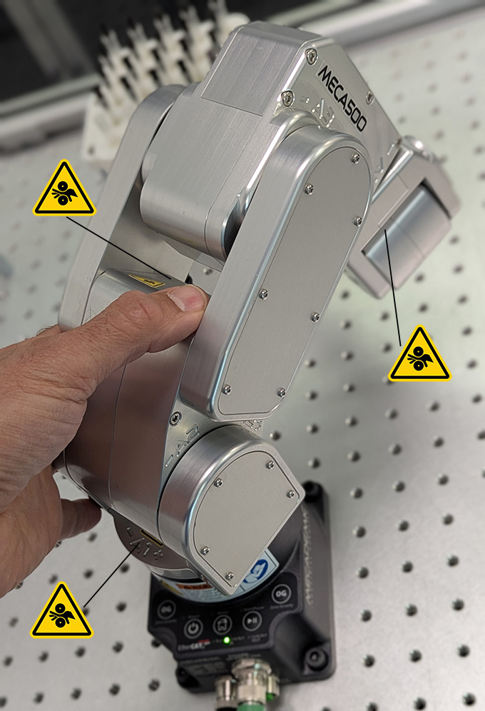 (a) pinching between some adjacent robot links
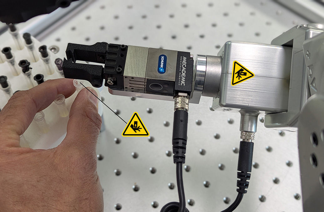 (b) pinning between end-effector and fixed objects
Figure 4 Examples of residual risks#
2.1.7. General safety guidelines#
Danger
In the shipping position, the robot can be temporarily deposited on its base (Figure 5a). In other robot positions (e.g., Figure 5b), the robot may tip and should not be placed on its base without fixing it. If the robot tips and falls from a height, it may cause an injury, and certainly get damaged.
 (a) correct
 (b) not correct
Figure 5 You may temporarily place the Meca500 on its base, but only if the robot arm is in its shipping position.#
Danger
Ensure the robot arm and end of arm tooling are securely fastened.
Do not modify or disassemble the robot arm or the PS200 module.
Do not touch the PS200 module for extended periods, while in operation.
Keep your head and hands away from the robot arm.
Ensure all clothing fits closely and remove jewelry before operating the robot. Secure long hair away from any moving parts.
Wear protective gloves and/or safety glasses when required for specific end-of-arm tooling and manipulated objects.
Warning
Handle the robot with care.
The Meca500 is equipped with brakes on its first three joints (the ones close to the base). When the robot is not activated, these brakes are automatically applied.
Do not overpower the robot brakes, unless there is an emergency!
Inspect the robot and PS200 module for damages. If either appears damaged, do not use them and contact us immediately.
Do not modify or disassemble the robot or the PS200 module. This will void your warranty.
Do not apply pressure to the cover plate on the bottom of the robot’s base.
Do not use or store the Meca500 in a humid environment or outdoors.
Do not operate the Meca500 at temperatures below 5°C or above 35°C.
Use only the PS200 module provided with your system.
Use only the Ethernet and DC-power cables provided. Contact us if you need longer cables.
2.2. Safety-related functions and operating modes#
The PS200 module features built-in safety functions and provides safety I/O digital control signals via one ports on the PS200 module for connection to PLCs and protective devices. All safety functions and I/O channels are designed in accordance with EN ISO 13849-1, using a Category 3 architecture to achieve Performance Level d (PL d).
The R4 version of the PS200 is shown in Figure 6. The R3 version is visually identical to the R4 version, except for the engravings. However, there are some hardware differences. Therefore, never use a PS200-R3 with a Meca500 R4 or a PS200-R4 with a Meca500 R3. The D‑Sub D15 dongle is, however, identical in both versions.
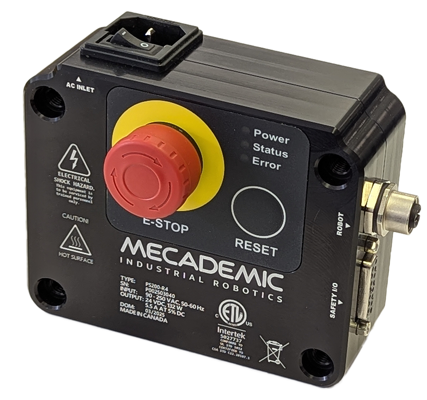
Figure 6 The PS200-R4 module#
The optional PS200NB-R4 module is identical to the PS200-R4, expect that is has no physical E-STOP and RESET buttons. Because of the lack of a physical Reset button, the PS200NB-R4 does not function with a safety bypass D‑Sub D15 dongle, which is therefore not supplied with the module.
2.2.1. Stop categories#
The robot can initiate only one stop categories—as defined in IEC 60204-1—depending on the circumstances, as shown in Table 3.
Stop Category |
Description |
|---|---|
1 |
When initiated, the robot decelerates in a controlled manner to a full stop within 150 ms. Power is removed from the motors after 380 ms regardless of system state. During deceleration, the robot may deviate from its initial path. |
2.2.2. Safety functions#
The Meca500’s safety functions are listed in Table 4. For each function, the table indicates the robot operating mode in which it is active and the resulting stop category.
Trigger |
Description |
Reaction |
|---|---|---|
E-Stop |
Emergency Stop |
Stop Category 1 |
P-Stop 1 |
Protective Stop 1 |
Stop Category 1 |
The E-Stop function of the Meca500 meets the performance level required by ISO 10218-1:2025 (5.4.2) which is PL=d with a circuit structure of Category 3 based on ISO 13849-1:2023. As per ISO 10218-1:2025 (5.4.2), a Category 3 structure means that:
A single fault in any subcomponent does not lead to the loss of the safety functions.
The single fault shall be detected at or before the next demand upon the safety function.
When the single fault occurs, the safety function is always performed and a safe state shall be maintained until the detected fault is corrected.
Safety equipment connected to the Protective Stop 1 function must meet the same requirements (PL=d and Category 3).
The E‑Stop and P-Stop 1 functions on the Meca500 are Stop Category 1, as per ISO 13850:2008 (4.1.4). Once the stop is initiated, the robot arm will stop any motion in a controlled manner in less than 150 ms. The power is removed from the robot (R3) or from the robot’s motors (R4) after 500 ms regardless of the state of the system.
The E-Stop and Protective Stop 1 inputs are redundant with two separate channels and monitoring circuitry is used to ensure that no tampering is possible. This means the inputs must switch states in tandem within 50 ms otherwise a Stop Category 0 will occur (power is removed from the motors).
2.2.3. Robot operating modes#
Because of the robot’s small size, it is not equipped with an operating mode switch and can operate only in automatic mode. Therefore, the robot does not require a three-position enabling device, but must be operated inside a safety enclosure (Figure 7). The PS200 module must be outside the safety enclosure.
Danger
The Meca500 is not designed for collaborative robot applications. Furthermore, it can operate only in automatic mode. Therefore, it must be operated inside a safety enclosure. Human operators must not enter the safeguarded zone while the robot motors are powered.
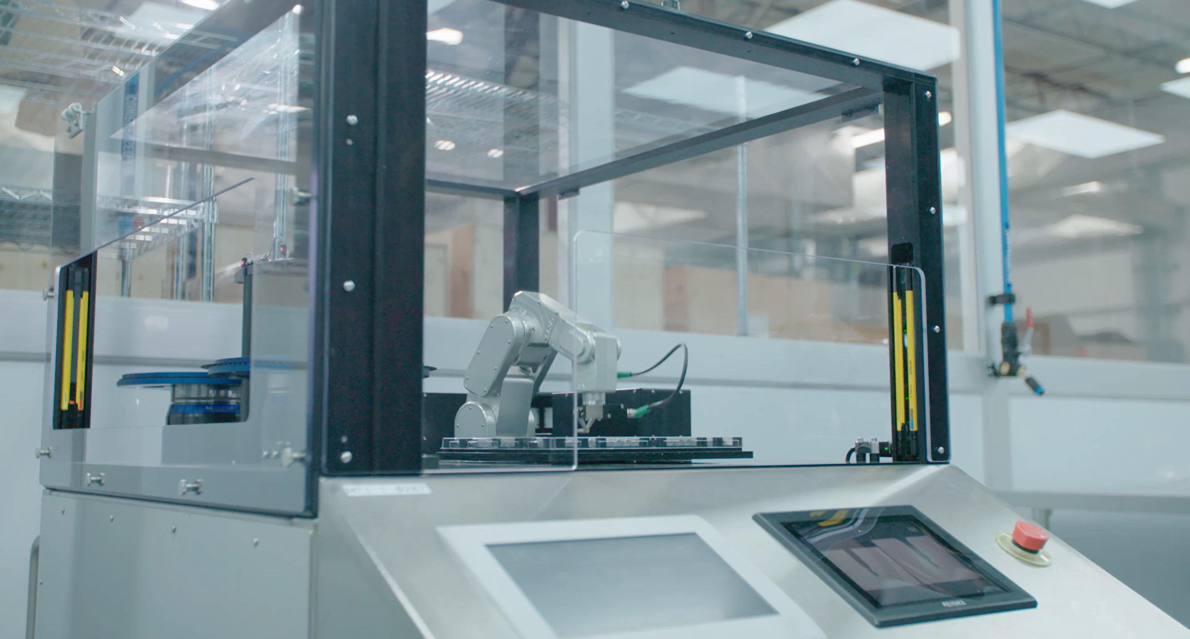
Figure 7 The Meca500 must be operated inside a safety enclosure (photo courtesy of Mati Therapeutics)#
2.3. Safety I/O connections#
After performing a risk assessment for your installation, you must design and connect the appropriate safety circuit to the D-Sub DB15 connector. Figure 8 shows the pinout of that connector. The following explains the different connections:
E-Stop function, four pins (E-Stop – A1, E-Stop – B1, E-Stop – A2, E-Stop – B2). This is the input that provides the E-Stop functionality to the robot.
P-Stop 1, four pins (P-Stop 1 – A1, P-Stop 1 – K1, P-Stop 1 – A2, P-Stop 1 – K2). This (redundant) safety input is intended for connecting optical curtains, or other presence-sensing safety devices.
Software stop, two pins (SWStop – A, SWStop – B).
Reset, two pins (Reset – A, Reset – K). This input is for wiring an external reset button that will have the same functionality as the one on the PS200 module.
Power status, two pins (Power Status – A, Power Status – B). This output indicates whether the robot motors are powered.


Figure 8 Pinout of the D-Sub DB15 connector on the PS200 module#
Warning
Electromechanical relays are not recommended for triggering P‑Stop 1, SWStop, and Reset functions due to the contact bounce during transitions. For the P-Stop 1 function, the use of such relays can cause a channel mismatch, leading to the PS200 module to detect a hardware fault. Solid-state relays, however, are suitable for these functions as they do not experience contact bounce.
Warning
Output signal switching device (OSSD) signals are not supported.
The following subsections provide examples and further important details regarding the connections of the Safety I/O port.
2.3.1. E-Stop function#
The external E-Stop performs the same function as the E‑Stop on the PS200 module. The terminals of the external E-Stop are connected in series with the E‑Stop on the PS200 module. Figure 9 shows two examples for the wiring of the four external E‑Stop terminals. You may also, for example, connect several E‑Stops in series or use a safety PLC. If you choose not to use any external E‑Stop, remember to wire the pins as in Figure 9b.
 (a) Wiring when an external E-Stop is used
 (b) Wiring when no external E-Stop is used
 (a) Wiring when an external E-Stop is used
 (b) Wiring when no External E-Stop is used
Figure 9 Examples of wiring of the external E-Stop connections#
Note
The E-Stop function is considered active whenever the external E-Stop circuit is open or the PS200 module’s E-Stop button is engaged.
Danger
Robot motor power is disabled when the E-Stop function is active.
This is a redundant safety signal. It must be connected using two independent signals.
All faults (differences) between signals will generate a non-resettable error.
2.3.2. P-Stop 1 function#
The E-Stop safety function and the P‑Stop 1 are inter-related in an OR logic. In other words, activating the E‑Stop safety function or removing power to the P‑Stop 1 has the same effect: removing power from the motors of the robot, from the brakes disengaging mechanisms, and from the robot’s EOAT (if R4) or in the complete robot (if R3).
Figure 10 shows the wiring diagram for the P‑Stop 1 terminals in the case of the R3 and R4 versions of the Meca500. The P‑Stop 1 signal would generally come from a safety PLC, which will be connected to a safety switch such as a safety light curtain or an interlock door switch.
Note, however, that in the R3 version, the current that reaches the PS200 module at the P‑Stop 1 terminals must be a 24 mA continuous forward current. This is why the use of proper resistances is compulsory in the R3 (see Figure 10a), or else you will damage the PS200 module.
In the case of the Meca500 R4, a current limiting circuitry has been implemented, and the use of a resistance is not necessary.
 (a) Wiring the P-Stop 1 in the Meca500 R3
 (b) Wiring the P-Stop 1 in the Meca500 R4
 (a) Wiring the P-Stop 1 in the Meca500 R3
 (b) Wiring the P-Stop 1 in the Meca500 R4
Figure 10 Examples of wiring the P-Stop 1 in the Meca500 R3 and R4#
Warning
In the Meca500 R3, you MUST USE RESISTANCES to limit the current applied to the P‑Stop 1 terminals to 24 mA, or else you will damage the PS200 module.
Danger
Robot motor power is disabled when P‑Stop 1 signal is logical low, at which point the P‑Stop 1 function is considered active.
The P-Stop 1 is a redundant safety function that must be wired through two independent signals.
All faults (differences) between signals will generate a non-resettable error.
2.3.3. Software Stop (SWStop) function#
The software stop is equivalent to sending the command PauseMotion or
ClearMotion, and is configurable with the command SetPStop2Cfg.
The SWStop signal would normally come from a safety PLC. Simple examples for the wiring
diagrams in the case of the R3 and R4 versions of the Meca500 are shown in
Figure 11. The same specifications for the input voltage and
current apply, as in the case of the P‑Stop 1, as shown in
Figure 11.
 (a) Wiring the SWStop in the Meca500 R3
 (b) Wiring the SWStop in the Meca500 R4
 (a) Wiring the SWStop in the Meca500 R3
 (b) Wiring the SWStop in the Meca500 R4
Figure 11 Examples of wiring the SWStop in the Meca500 R3 and R4#
Warning
In the Meca500 R3, you MUST USE RESISTANCES to limit to current applied to the SWStop terminals to 24 mA, or else you will damage the PS200 module.
Danger
In contrast to P-Stop 1, the SWStop function is considered active when the SWStop signal is logical high, a state that prevents robot movement while motor power remains applied.
The SWStop function is not safety-rated and must not be treated as a protective stop.
2.3.4. Reset function#
The external reset connection performs the same function as the Reset button on the PS200 module. Activating either of these yields the same action, as long as the other is deactivated. The terminals of the external reset are connected in parallel with the Reset on the PS200 module.
The external reset signal would normally come from a safety PLC. Simple examples for wiring diagrams in the case of the R3 and R4 versions of the Meca500 are shown in Figure 12. The same specifications for the input voltage and current apply, as in the case of the SWStop, as shown in Figure 12.
 (a) Wiring the external reset in the Meca500 R3
 (b) Wiring the external reset in the Meca500 R4
 (a) Wiring the external reset in the Meca500 R3
 (b) Wiring the external reset in the Meca500 R4
Figure 12 Examples of wiring the external reset in the Meca500 R3 and R4#
Warning
In the Meca500 R3, you MUST USE RESISTANCES to limit to current applied to the reset terminals to 24 mA, or else you will damage the PS200 module.
Note
The E-Stop, P-Stop 1 and SWStop functions must be deactivated when sending the Reset signal.
Pulse logical high for at least 15 ms but less than 1 s to reset robot. Recommended pulse duration is between 50 ms and 500 ms.
2.3.5. Power status#
The power status terminals provide an output signal that corresponds to the power state of the robot (in the case of R3) or of the robot motors (in the case of R4). The current on these terminals is limited to 60 mA, and the voltage to 24 V (DC). There is no difference between the R3 and R4 with regards to the power status connection.
Two examples of wiring the power status terminals are given in Figure 13.
 (a) Wiring the power status signal to a LED
 (b) Wiring the power status to a safety PLC
 (a) Wiring the power status signal to a LED
 (b) Wiring the power status to a safety PLC
Figure 13 Examples of wiring the power status in the Meca500 R3 and R4#
Warning
In both the R3 and R4 versions of the Meca500, the maximum voltage applied at the power status terminals must be 24 V (DC), and the maximum current must be limited to 60 mA.
Danger
The Power status signal is logical high when robot motor power is enabled.
The Power status signal is not safety-rated.
2.3.6. D-Sub DB15 dongle (first time use and maintenance only)#
The provided D‑Sub DB15 dongle can be used to temporary bypass safety connections as during first time use or during maintenance. Connect the dongle to the D‑Sub interface of the PS200 module (Figure 14). This would deactivate the external P‑Stop 1 and E‑Stop connections.
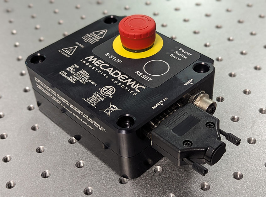
Figure 14 D-Sub DB15 safety dongle installed#
Warning
Connect the D-Sub dongle to the power supply interface, while the PS200 module is still switched off. NEVER CONNECT OR UNPLUG THE DONGLE WHILE THE MODULE IS ON.
Warning
The D-Sub dongle cannot be used with the PS200NB-R4, which has no physical E-Stop and Reset buttons.
Danger
The D-Sub dongle is a bypass device, to be used during setup and maintenance only. You must wire the appropriate safety I/O connections when using the robot in production mode (see Section 2.3).
Danger
Stand away from the robot when it is activated, wear safety goggles and close-fitting clothing, keep long hair securely tied back and be attentive and alert. In case of an emergency, press the E‑Stop button (on the PS200 module) immediately.
2.4. Further safety information#
Figure 15 shows a description of the main components of the Meca500 robot arm.


Figure 15 Meca500 robot arm#
2.4.1. Brakes and limitations#
As already mentioned, the Meca500 has brakes on joints 1, 2 and 3 only. Therefore, when the robot is deactivated, powered off, or put in safety stop (E‑Stop or Protective Stop 1), the brakes on these joints be immediately applied and the joints will be immobilized instantly. Simultaneously, joints 4, 5, and 6 will become free. This minimizes the risks of pinning and pinching from the wrist and the end-effector. However, beware that the end-effector might slowly move downwards under the effects of gravity, as shown in Figure 16. Depending on the type of end-effector used, this residual motion might lead to an injury.
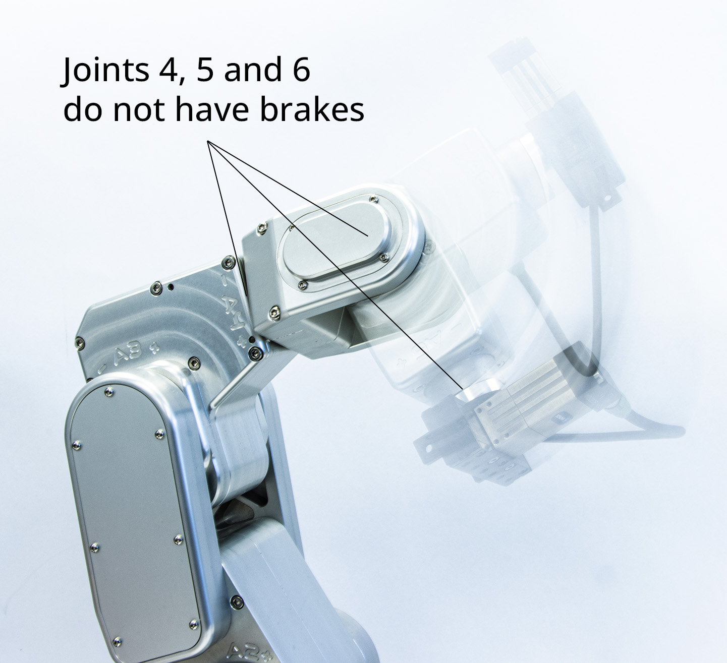
Figure 16 When the robot is deactivated, the end-effector will slowly move downwards under the effects of gravity#
Danger
Beware that the end-effector might slowly move downwards under the effects of gravity or inertia when you deactivate the robot (e.g., by pressing the E-Stop button).
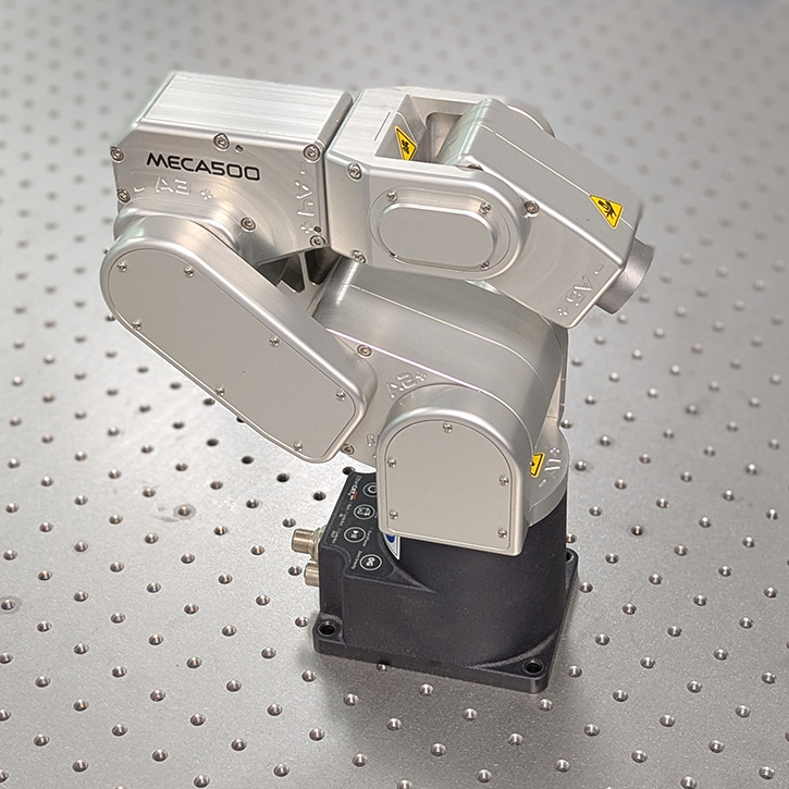
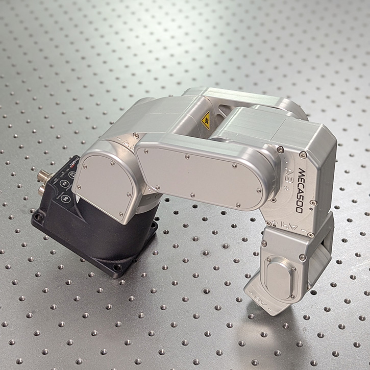
In addition, remember that the brakes used on joints 1, 2 and 3 are emergency brakes, not locking brakes. Therefore, if you leave the robot in a configuration where the robot’s upper arm and forearm are nearly horizontal, the robot will slowly fall down under the effects of gravity, especially if you have the maximum payload. For example, if you deactivate the robot in the configuration shown in Figure 17(a), the robot’s gripper might eventually collide with the table.
Warning
Before leaving the robot deactivated or powered off for an extended period of time, bring it to a position that minimizes the static torques on joints 1, 2 and 3.
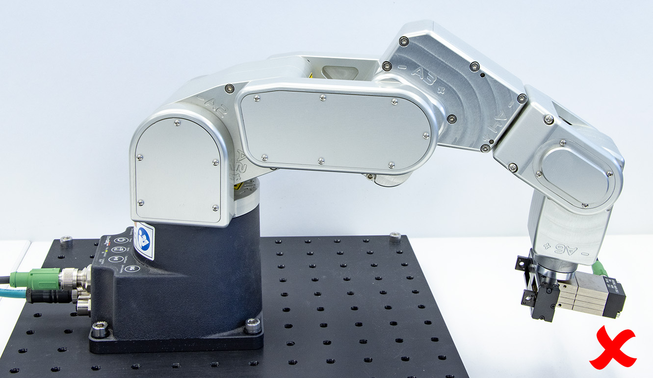 (a) Do not leave the robot deactivated like this
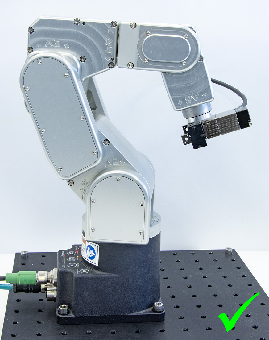 (b) Do leave it like this
Figure 17 Before leaving the robot for a long period of time, move it to a position that minimizes the joint torques#
2.4.2. Releasing the brakes#
You can disable the brakes of joints 1, 2 and 3, ONLY if the robot motors are powered AND the robot is deactivated. (There are no purely mechanical means for doing so.) This means that the E-Stop or protective stop should not be activated, which does not meet the requirements of ISO 10218-1:2025.
The only situation where you might need to disable the robot brakes and move the robot by hand, is if you are about to power up the robot, but some of its links are leaning against an obstacle, thus preventing a joint to rotate in both directions. This slight rotation is part of the homing procedure, which is necessary only during the first activation of the robot (after a power-up). That said, in such a scenario, always try to use the recovery mode first, which does not require homing. This would avoid having to disable the brakes.
If you do need to disable the brakes, with a safety feature like a light curtain installed to prevent entry into the robot’s safety zone without triggering the P‑Stop 1 (as in Figure 7), disengaging the robot’s brakes while manually holding the robot becomes impossible. To proceed, in the case of PS200-R3 and PS200-R4, you would need to temporarily swap your current D-Sub connection with our D-Sub dongle.
Danger
If your hands are penetrating the working zone of the Meca500, keep your fingers away from the pinch points of the robot. The procedure for disengaging the brakes of the robot while holding the robot does not meet the requirements of ISO 10218‑1:2025.
Once you can approach the robot without triggering a P‑Stop 1 event, turn on the power and ensure that the E‑Stop on the PS200 module is not pressed. Next, to minimize the risks that a remote commands activates the robot, unplug the Ethernet cable controlling the robot. Then, while the robot is still deactivated, press one of the two 0G buttons on the base of the robot continuously while holding the robot with your other hand. After 3 seconds, you will hear the deactivation of the brakes. Continue holding the 0G button pressed and move the robot links away from obstacles. Finally, release the 0G button, and move away from the robot.
Note
Note that in the case of a collision, the robot is not deactivated and you can easily reset the motion error and jog the robot away, without entering the safety enclosure of the robot. If you are worried about damaging your equipment, it is advisable to first enter recovery mode (as described in the Programming Manual).
2.4.3. Stopping times and distances#
As already mentioned, in the Meca500, when an E-Stop is applied, the PS200 module sends a signal to the robot to decelerate to a complete stop and after 450 ms removes power from the robot (R3) or from the motors (R4). Once power is removed from the motors, the brakes are automatically applied.
Table 5 shows values for the worst possible scenario, where the stop signal from the PS200 module is not detected by the robot. These are only theoretical values, because applying the brakes without decelerating the robot will permanently damage the robot. The actual values will be slightly larger due to the slip of the brake pads.
Danger
Note that only the E-Stop function is designed to achieve PL=d. Therefore, we cannot guarantee that the robot will immediately detect the signal from the power supply.
Joint |
Stopping distance |
Stop time |
|---|---|---|
1 |
67° |
0.450 s |
2 |
67° |
0.450 s |
3 |
81° |
0.450 s |
In normal, fault-free operation, the stopping times and distances for an E-Stop (category 1) at 100% speed and payload are presented in Table 6. All test results are for a single joint moving at a time, while the other joints are positioned in a way that the arm is fully stretched (i.e. worst condition). The results are valid only for an installation where the axis of joint 1 is parallel to the direction of gravity.
Joint |
Stopping distance |
Stop time |
|---|---|---|
1 |
6.2° |
0.104 s |
2 |
6.2° |
0.125 s |
3 |
8.1° |
0.129 s |
2.4.4. Joint limits#
Because of the robot’s compact dimensions, mechanical means to limit joint range have not been incorporated. It is possible to design a fixture that can be attached to the robot’s base and that limits mechanically the range of joint 1. However, remember to not modify the robot itself (e.g., by removing screws from the robot).
The robot’s joint limits can be reduced by software means using the MecaPortal or the
command SetJointLimits. The new software limits remain active even after
power shutdown. These software limits are not safety rated.
Danger
Due to the extremely compact size of the robot, there are no provisions for adjustable hardware joint limits.
2.4.5. Joint torque limits#
Once a robot is activated and homed, you can also reduce the joint torque limits using
the command SetTorqueLimits. However, the joint torque limits are reset to 100%
every time, the robot is reactivated. Furthermore, these joint torque limits are not
safety rated.
2.4.6. Local control#
The Meca500 provides no built-in means of local control. It is therefore the responsibility of the robot integrator to equip the control station with a suitable local interface, such as keyed switch or safety-gate interlock, that lets an operator enable or disable the remote connection whenever local intervention is required. The control station must be designed and installed in full compliance with all applicable local laws, regulations, and safety standards.
2.4.7. Loss of Ethernet connection#
When using the MecaPortal web interface or any other TCP/IP client, as soon as the robot
detects a loss in the connection while moving, it will stop within 0.1 s. To prevent
delays due to the use of Ethernet switches, at all times (not only while the robot is
moving), use the ConnectionWatchdog command (available since firmware 10.1).
2.4.8. Locking up the robot system#
To prevent unauthorized or accidental powering of the robot, we suggest unplugging the AC cord and using a detachable IEC Plug Lockout device such as the one from Brady.