4. Installing the robot system#
Before operating your Meca500, you must fix solidly its base with four M6 screws, at 3 Nm, with at least 6 mm of thread engagement. We typically use metric breadboards such as those from Thorlabs, but you can also use our adapter plate (MUAP01.zip) or build your entire robot cell at Vention. We recommend that you use three kinematic positioners to constrain your base, so that you can always remove and then install it in the exact same location. Our adaptor plate, for example, incorporates three locating pins.
The dimensions of the robot base are shown in Figure 21 and an example of installation is shown in Figure 22. Note that you can install the robot base in any orientation. The robot will automatically detect the angle between the axis of joint 1 and the gravity vector (no need to manually specify this angle). Also, note that you can mount the robot’s base on a mobile body (e.g., on the carriage of a linear guide), but only if you do not intend to move the robot’s joints, while the robot’s base is accelerating with respect to the ground.
Warning
Ensure that the mounting surface is perfectly flat and that nothing exerts pressure on the cover at the bottom of the robot’s base.
Danger
Secure the robot base firmly using four M6 screws tightened to a torque of 3 Nm. Periodically inspect the screws to ensure they remain properly tightened.


Figure 21 Dimensions of the robot base#
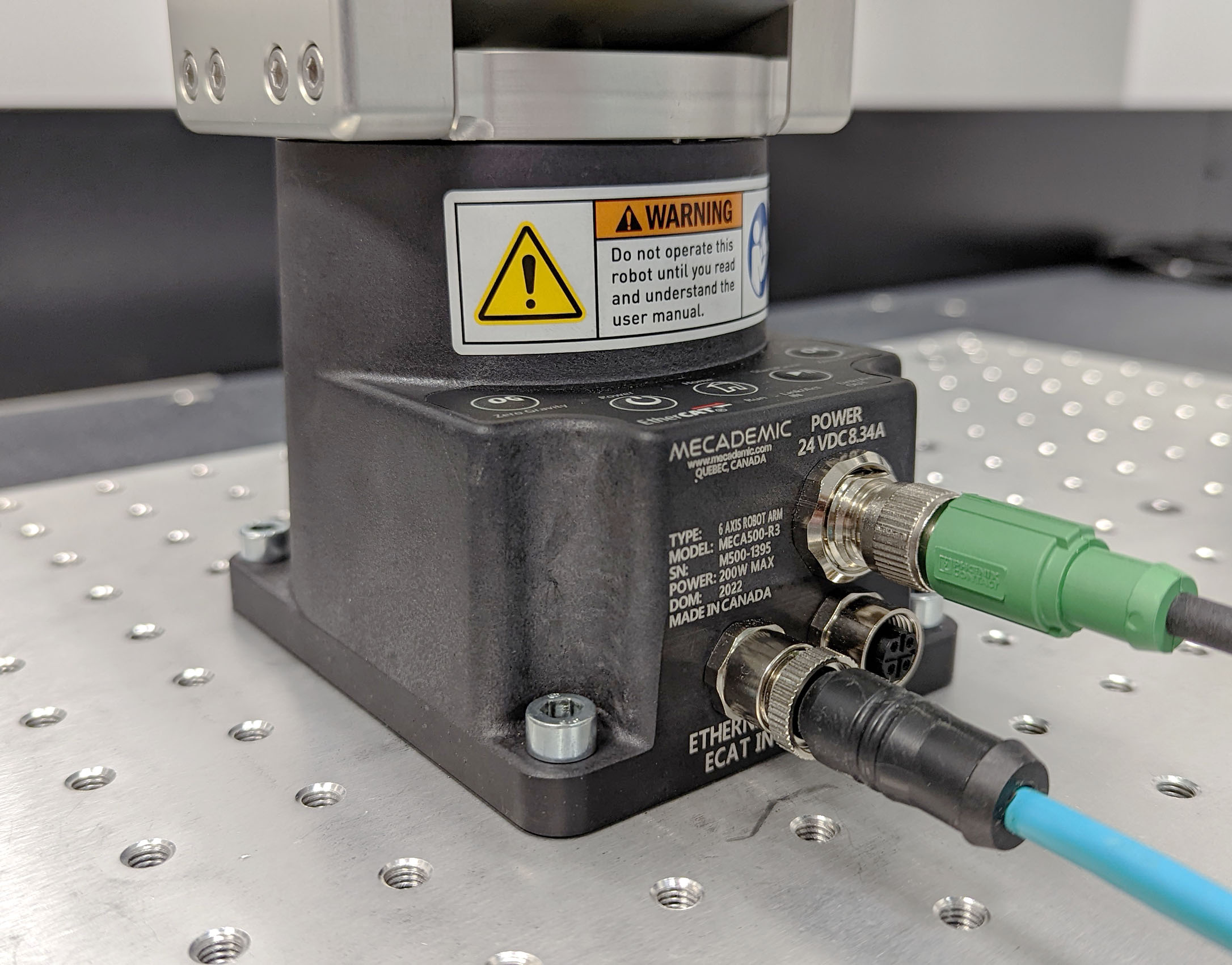
Figure 22 The robot base installed, with the connectors attached#
Do not install any end-effector yet. We will cover this topic in Section 6.
Next, securely mount the PS200 module using four M6 screws (Figure 23) at a location sufficiently close to the robot’s base to allow connection with the 2-meter DC cable provided, but outside the robot’s safety enclosure. Unless you are using an external emergency stop wired via the D-Sub connector, you must fix the PS200 at a location that makes the integrated E-Stop button readily accessible by an operator.
Warning
To improve heat dissipation, mount the PS200 module onto a solid metal plate.


Figure 23 Dimensions of the PS200 module#
Next, attach the circular connector of the Ethernet cable to the ETHERNET1 port on the robot’s base and connect the RJ-45 jack to your computer or router (Figure 22). The two Ethernet ports on the robot base act as a bridge, so you can daisy-chain several Meca500 robots, or connect an Ethernet I/O module on the ETHERNET2 port.
Finally, use the DC power cable provided to connect the unpowered PS200 module to the robot’s DC power connector (Figure 22). Make sure the connectors are completely screwed, or else you may damage the robot. Then, connect the PS200 module to your country-specific AC power cord (not provided).
Warning
Always connect the DC power cable before connecting the PS200 module to an AC outlet. Always disconnect the PS200 module from the AC outlet before disconnecting the DC power cable.