5. Operating the robot system#
This section presents the basic procedures for setting up and operating the Meca500 robot system. For further details, refer to the MecaPortal Operating Manual (MC-OM-MECA500), which describes the web interface of the robot, and to the Programming Manual (MC-PM-MECA500).
5.1. First-time use#
Danger
For prototyping purposes, the Meca500 comes with a safety bypass DB15 dongle (recall Section 2.3.6). To start using the MCS500, plug the D‑Sub dongle, while the PS200 module is unpowered. Once you have become acquainted with the Meca500 and performed your risk assessment, remove the dongle and wire your safety I/O connections (see Section 2.3).
5.1.1. Configuring your Ethernet connection (first time use)#
Configure your computer Ethernet connection with a static IP address, on the same subnet as the robot’s default IP address, i.e., 192.168.0.100. The way to do this differs from one operating system to another. Figure 24 shows how to do this in Windows and in Linux.
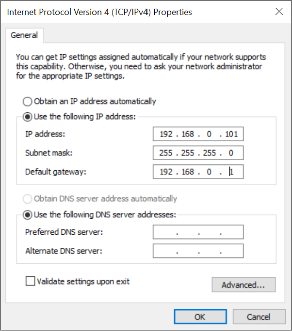 (a) Windows
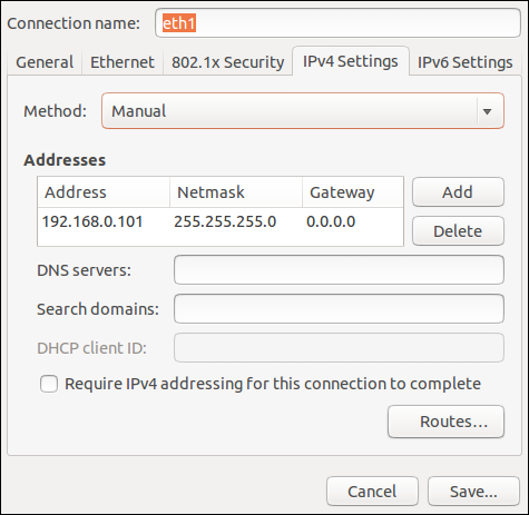 (b) Linux
Figure 24 Two examples of how to configure the IP address of your computer#
5.2. Power-up procedure#
5.2.1. Powering the robot#
Turn on the PS200 module. The green LED on the PS200 module (next to “Power”) will be illuminated.
Make sure the E-STOP button is disengaged by twisting it counter-clockwise.
In the case of Meca500 R3, activate the Reset function (e.g., press the RESET button) to provide power to the robot.
You will hear a clicking sound coming from the PS200 module, and the robot’s LEDs will start flashing for a few seconds while the robot’s controller is booting. Once the controller ready, the Power LED on the robot’s base will start flashing intermittently.
Depending on which of the two Ethernet ports was used in step 1, the Link/Act IN (for ETHERNET1) or Link/Act OUT (for ETHERNET2) green LED will stop flashing and remain illuminated, but only once the robot has finished booting.
In the case of the Meca500 R4, activate the Reset function (e.g., press the RESET button) to provide power to the robot’s motors.
5.2.2. Connecting to the robot#
Open (preferably) the latest version of Google Chrome and type Meca500’s default IP address 192.168.0.100 in the address bar.
Meca500’s web interface, called MecaPortal, should load instantaneously (Figure 25). The MecaPortal will be described in detail in a separate manual (MC-OM-MECA500).
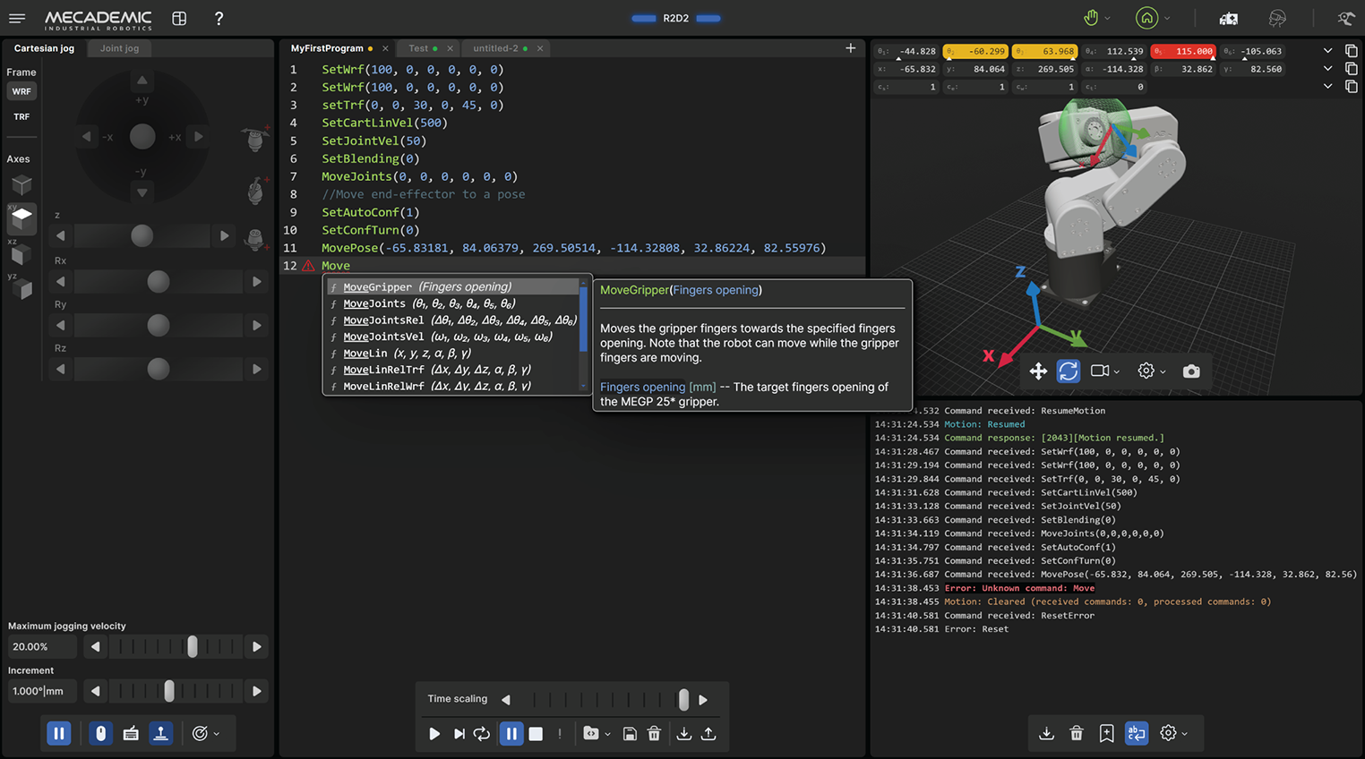
Figure 25 Overview of the MecaPortal#
5.2.3. Changing the robot’s network configuration (optional)#
Click on the connection state button on the top right of the MecaPortal and select
 “Control” (see Figure 26).
Click on the configuration menu button,
 , in the top left corner of the
MecaPortal and select “Network configuration”.
, in the top left corner of the
MecaPortal and select “Network configuration”.Depending on your configuration, activate the toggle DHCP to automatically receive an address from your router or leave untoggled to force a specific IP. You don’t need to reboot the robot; the new configuration will be applied as soon as you click on the Apply button (Figure 27).
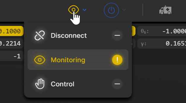
Figure 26 Connection state button#
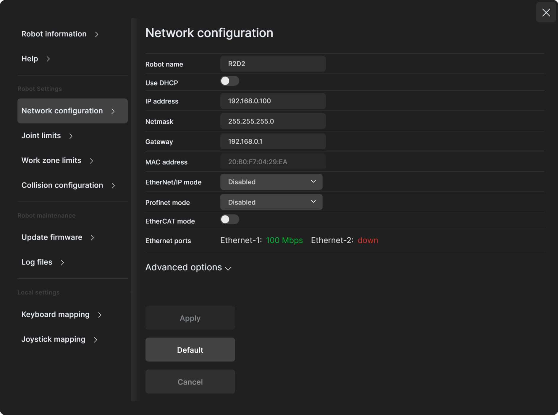
Figure 27 Changing the robot’s network configuration#
5.2.4. Activating and homing the robot#
Click the  button in the menu bar and select
  “Activate then
Home”.
“Activate then
Home”.
Warning
The robot will move slightly during homing. Before homing it, make sure that there is no risk for mechanical interference.
5.2.5. Testing joint 6#
After homing, type “0” in the text field next to θ6 (joint 6) in the Jog joint tab and press Enter. The flange of the robot must be exactly as in Figure 28. Later, when you connect tooling to the flange of the robot, you must remember the correct orientation of the tooling when joint 6 is at zero degrees, and continue to perform this test every time you start your robot.
If the flange is rotated ±120° with respect to the orientation shown in Figure 28, perform the procedure given below, before continuing to use the robot.
Note
The range of the absolute encoder of joint 6 is only ±420°. Therefore, you must always rotate joint 6 within that range before switching the robot off. Failure to do so may lead to an offset of ±120° in joint 6. If this happens, unpower the robot and disconnect your tooling. Then, power up and activate the robot, perform its homing, and zero joint 6. If the screw on the robot’s flange is not as in Figure 28, then rotate joint 6 to +720°, and deactivate the robot. Next, reactivate it with the command ActivateRobot, which reinitializes the drives, then home the robot, and zero joint 6 again. Repeat one more time if the problem is not solved.

Figure 28 Joint 6 at zero degrees#
5.2.6. Moving the robot#
A six-axis robot arm is a complex mechanism and no matter how intuitive its programming interface is, the robot will still have limits. These limitations are not always obvious. For example, in any six-axis robot arm, there are often paths that the robot cannot follow, even though they seem to be inside the robot’s workspace. The workspace of a typical six-axis robot is a very intricate six-dimensional entity.
Note
If you know nothing about orientation representations and robot singularities, we strongly advise you to read some introductory notes on robotics and our tutorials on Euler angles and on robot singularities.
After homing, click the  button in the jogging panel and select “Zero all
joints”. The robot will move all of its joints to their 0° positions. In this robot
joint set (shown in Figure 18), the robot is in a so-called wrist
singularity. Most industrial robots cannot move in Cartesian mode from such a
singularity. In order to simplify the use of the Meca500, as of firmware 9, we have
implemented an algorithm that allows the robot to move through such a singularity.
button in the jogging panel and select “Zero all
joints”. The robot will move all of its joints to their 0° positions. In this robot
joint set (shown in Figure 18), the robot is in a so-called wrist
singularity. Most industrial robots cannot move in Cartesian mode from such a
singularity. In order to simplify the use of the Meca500, as of firmware 9, we have
implemented an algorithm that allows the robot to move through such a singularity.
Note
The Cartesian coordinates displayed above the robot in the web interface are those of the Tool Reference Frame (TRF) with respect to the World Reference Frame (WRF). Both frames are displayed in the web interface. By default, the TRF is located at the flange of the robot and the WRF at the bottom of the robot’s base (as in Figure 29). The origin of the TRF is called the TCP (Tool Center Point).
Note
We use Euler angles (α, β, γ) to define the orientation of a second reference frame with respect to a first one. More specifically, if we consider both frames initially coincident, we rotate the second frame about its x axis at α degrees, then about its y axis at β degrees, and finally about its z axis at γ degrees. This Euler-angle convention is sometimes referred to as XY’Z’’, or as XYZ intrinsic (body-fixed) rotations.
Thus, for example, you can simply go to the Cartesian tab of the jogging menu, and with the TRF option selected, press the right arrow button of the x jogging bar. Alternatively, you can perform the same kind of linear motion by following any of these steps:
Clear the programming text field, type MoveLin, and press
 .
.
OR
Clear the programming text field, type MoveLinRelTrf, and press
.
Figure 29 shows the resulting robot position.
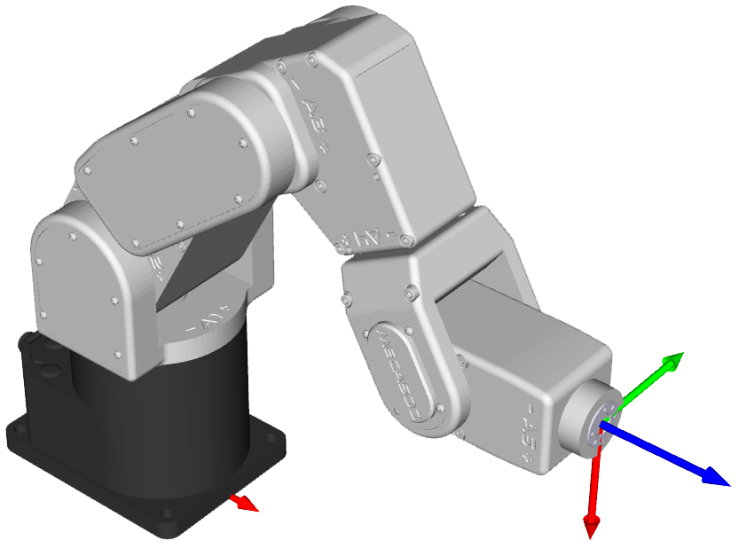
Figure 29 Robot position when the TRF is at x = 250 mm, y = 0 mm, z = 150 mm, α = 0°, β = 90°, γ = 0° with respect to the WRF#
5.2.7. Testing the E-Stop function and the brakes (first time use)#
Execute a movement command and, while the robot is still moving, activate the E‑Stop function (e.g., by pressing the E-STOP button on the PS200 module). The PS200 module completely cuts power to the robot, in the case of R3 version, or only to the robot motors and Mecademic’s EOAT, in the case of R4 version. In both cases, the robot brakes will be automatically applied to joints 1, 2 and 3. If joints 1, 2 or 3 continue to move, or if you notice that even after powering off the robot, one or more of these joints can be as easily rotated by hand as joints 4, 5, and 6, cease using the robot immediately and contact us immediately.
To use the robot again, you must power on the robot, deactivate the E-Stop function, activate the Reset function, then activate and home the robot.
5.3. Power-off procedure#
5.3.1. Zeroing the robot joints#
It might be a good idea to always bring the robot joints to their zero positions before turning the robot off. This can be done in two ways:
send a MoveJoints command with all arguments equal to 0
OR
click the button in the jogging panel and select “Zero all joints”.
If you cannot zero all joints, you must at least bring joint 6 inside the range ±420° before switching the robot off (recall Section 5.2.5).
5.3.2. Deactivating the robot#
To deactivate the robot
clear the
button and then select “Deactivate”
OR
send the DeactivateRobot command via the programming editor.
Warning
Recall that there are no brakes on joints 4, 5, and 6. As soon as you deactivate the robot, the end-effector will slowly tilt down under the effects of gravity.
Note
If you accidentally close your web interface before deactivating the robot, the robot will stop (in case it was moving) but will remain activated.
5.3.3. Disconnecting the robot#
To disconnect the web interface from the robot, select the  option
from the connection state group.
option
from the connection state group.
Danger
If you disconnect the web interface from the robot before deactivating the robot, the robot will stop moving.
5.3.4. Removing power#
Finally, unplug the PS200 module from the AC outlet or switch the PS200 module off.
Warning
Never detach the DC power connector from the robot’s base, before unplugging the PS200 module’s AC power cord from the AC outlet or switching the PS200 module off.
5.4. Robot control panel#
The set of buttons and LEDs on the robot’s base is called the robot’s control panel (Figure 30). The meanings of the LEDs and the functionalities of the buttons will be summarized in what follows.
Note that these buttons and LEDs are intended mainly for development and demonstration purposes, as they will not be physically accessible and possibly not visible during a normal operation of the robot, where the robot is fenced. The information conveyed from these LEDs and the actions controlled by these buttons are all available in the MecaPortal. The only exceptions are the Link/Act LEDs and the Run LED. The information conveyed by the Run LED, used only when the robot is controlled via EtherCAT, is accessible by the EtherCAT master.
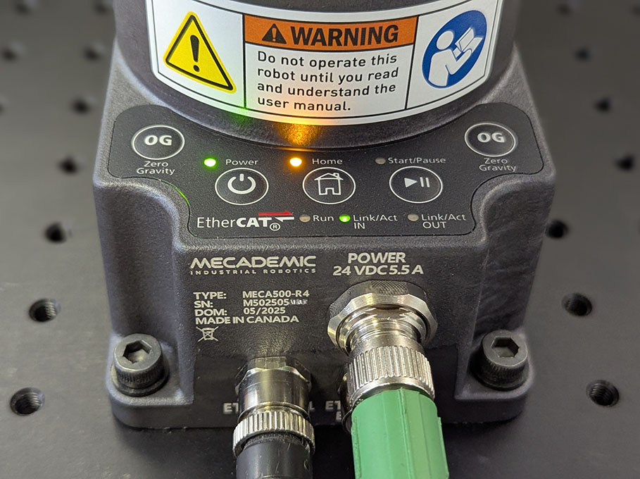
Figure 30 Robot control panel#
5.4.1. LEDs#
Power, Home, and Start/Pause LEDs
Table 11 summarizes the different states of the main three LEDs on the control panel of the robot as well as their meanings.
Situation |
Power (green†) |
Home (yellow) |
Start/Pause (yellow) |
|---|---|---|---|
Robot is booting |
slow blink (all three LEDs blink simultaneously once every second) |
||
Robot is powered but deactivated |
1 flash per second - |
off |
off |
Robot is being activated |
slow blink (0.5 s on, 0.5 s off) |
off |
off |
Robot is activated |
on |
– |
– |
Robot is not homed |
– |
off |
off |
Robot is being homed |
on |
slow blink (0.5 s on, 0.5 s off) |
off |
Robot is homed |
on |
on |
– |
Robot is not moving |
– |
– |
off |
Robot is moving |
on |
on |
on |
The Start/Pause button was pressed and program 1 is about to start |
on |
on |
slow blink (0.5 s on, 0.5 s off) |
Robot is in error mode |
all three LEDs flash simultaneously once every second |
||
The robot firmware is being updated |
quick traveling blink (each LED blinks quickly in sequence, once every second) |
||
Network reset |
first flash simultaneously eleven times, and then blink several times sequentially |
||
† For robots manufactured before May 2025, the Power LED was red, which did not comply with the requirements of IEC 60204-1.
Link/Act IN and Link/Act Out LEDs
Both LEDs are green and flash when there is network activity in the corresponding Ethernet port. The LEDs function in the same manner as on a normal Ethernet RJ-45 port.
Run LED
Used only when the robot is controlled via EtherCAT (see the Programming Manual).
5.5. Offline mode (for demonstrations only)#
You can store a program in the robot and execute it without an external computer. This program is kept, even after power off, until replaced by another one. You can save up to 500 programs, but only the first one can be executed from the robot control panel.
5.5.1. Saving the program via the MecaPortal#
You can use the MecaPortal to write programs to the robot, as described in The code editor panel of the MecaPortal operating manual. To write a program that can be executed by pressing the Start/Pause button on the robot’s base, follow the steps below:
Open the web portal and write the program in the code editor panel.
To run the program on infinite loop, insert the command SetOfflineProgramLoop. (The checkbox
 has no effect on the
execution of the program.)
has no effect on the
execution of the program.)Click on the
 button and change the name of the program to “1”.
5.5.2. Running a program#
To execute the program 1, make sure there is no user connected to the robot and press the Start/Pause button on the robot base. The Start/Pause LED will flash rapidly for three seconds, after which the robot will start executing the program.
Danger
Immediately after pressing the Start/Pause button on the robot’s base, move away your hand and stay outside the robot’s reach.
It is highly recommended to run programs using any of the communication protocols, rather than by using the button on the robot control panel, which not only presents certain safety risks but can only execute program 1.
5.6. PS200 module#
5.6.1. Emergency, protective, and software stops#
Once you power up the robot, you must make sure the E-Stop function is deactivated. Then, activating the Reset function sends power to the robot motors and to the EOAT (if R4) or to the complete robot (if R3).
Once the robot is activated and homed, activating the E‑Stop function at any time instantly sends a signal to the robot to rapidly decelerate and come to a complete stop. The PS200 module then waits for a signal from the robot indicating that the robot is completely stopped, and as soon as that signal is received, but no later than in 500 ms, the PS200 module completely cuts power to the robot, in the case of R3 version, or only to the robot motors and Mecademic’s EOAT, in the case of R4 version. In both cases, the robot brakes are then automatically applied to joints 1, 2, and 3. To use the robot again, you must deactivate the E‑Stop function, and activate the Reset function, then activate and home the robot.
Of course, you will also need to manage the stream of commands being sent to the robot. For example, if a PLC sends commands to the robot, while the robot is powered off, the program that runs on your PLC will need to be able to detect and manage this situation. To do so, you can get a signal from the PS200 module that an E‑Stop has been engaged by connecting your PLC to the D‑Sub connected, as will be explained in the following pages. In the case of the R4 version, the event is also reported by the robot controller.
5.6.2. LEDs on the PS200 module#
The PS200 module is equipped with three LEDs. As long as the PS200 module is switched on (using its on/off button) and connected to an AC source supplying 90–250 V at 50–60 Hz, the green LED next to “Power” stays illuminated. Applying AC voltage outside this range may damage the PS200 module.
Once the PS200 module is switched on, the yellow Status LED indicates the status of the PS200 module. If the yellow LED is off, you need to activate the Reset function, which sends power to the robot. If the proper Meca500 is correctly connected to the power supply, the yellow LED will turn on and stay lit.
If, in any situation, the yellow LED blinks regularly, it indicates that an emergency stop or the external SWStop is activated. You need to deactivate the E‑Stop function or remove the cause for the SWStop and then activate the Reset function.
If the yellow LED flashes in sets of two, it indicates that the Reset function has been activated for too long. To resolve this, ensure the Reset function is deactivated, then activate it again briefly.
Finally, the red Error LED indicates if there is a problem with the PS200 module or with some of the connections to the D‑Sub interface. If the red LED flashes (0.1 s on, 0.9 s off), either there is no robot connected to the PS200 module or the robot connected is an old version that is not supported by this PS200 module. If the red LED illuminates in sets of two quick flashes, the robot has detected a problem and sent a request to the PS200 module to be shut down. If this happens, contact us. If the red LED blinks in regular intervals (0.5 s on, 0.5 s off), this means that there is either a problem in your external emergency stop or Stop Category 1 connections or in our PS200 module. If you don’t see any problem in your connections, contact us. Finally, if the red LED is constantly lit, there is a problem with the PS200 module. Switch off the PS200 module and contact us.
Table 12 summarizes the different states of the three LEDs as well as their meanings.
Situation |
Power (green) |
Status (yellow) |
Error (red) |
|---|---|---|---|
PS200 module is switched off. |
off |
– |
– |
PS200 module is switched on. |
on |
– |
– |
Robot not powered. Activate Reset function. |
– |
off |
– |
Robot not powered and Stop Cat. 1 pressed or dongle not plugged. Remedy situation and activate Reset. |
– |
slow blink (0.5 s on, 0.5 s off) |
– |
Reset active too long. Deactivate then reactivate briefly. |
– |
2 flashes per second |
– |
Robot powered |
– |
on |
– |
No error |
– |
– |
off |
No proper robot connected. |
– |
– |
1 flash per second |
Robot fault—power shut down. Contact us. |
– |
– |
2 flashes per second |
Stop Cat. 1 issue. Check wiring or contact us. |
– |
– |
slow blink (0.5 s on, 0.5 s off) |
Voltage error. Power cut, locks in power-down state. |
– |
– |
on |