6. Installing an end-effector#
The Meca500 comes with a proprietary tool I/O (input/output) port located at the robot extremity (Figure 31). However, this tool I/O port is reserved uniquely for our end-of-arm-tooling (EOAT), i.e., our electric grippers MEGP 25E and MEGP 25LS, and our pneumatic module MPM500. We do not share the pinout of this port or its custom-made communication protocol. To install our grippers or pneumatic module, refer to their user manuals (MC-UM-MEGP25 and MC-UM-MPM500).
If you want to use any other end-effector with the Meca500, you will need to control it independently from the Meca500. You can attach the cabling of your end-effector along the robot arm using adhesive-backed tie mounts. Finally, you must fix the end-effector to the robot’s flange (Figure 32) using four M3 screws tightened at 1.5 Nm, and, optionally, one Ø3 locating pin, all of properly selected length.
Danger
Keep the robot unpowered while installing/removing a tool to its flange.
Do not exceed the robot payload (0.5 kg).
Do not exceed 3.4 Nm for the moment load on the robot flange.
Securely fasten the tool to the robot flange.
Figure 19 and Figure 20 present the payload charts of the Meca500 (R3 and R4), where each curve indicates the limit corresponding to the position of the payload’s center of gravity. Note that the payload includes everything attached to the robot flange, e.g., the gripper, its fingers and the part being handled.
Note that since joint 6 is multi-turn, there is no way of knowing the angle of joint 6 (even approximately), unless the robot is activated and homed. Therefore, prior to mounting an end-effector, it is important that you activate and home your robot, rotate joint 6 to its zero position, and finally unpower the robot. However, if the screw on the flange of the robot is not as in Figure 31 when θ6 = 0°, then you need to follow the procedure described in Homing of the Programming Manual.
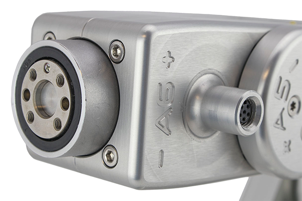
Figure 31 Closeup of the mechanical interface (flange).#
Note
The flange is the Ø20 disk, inside the black isolation ring, and is the only one to rotate when joint 6 rotates.


Figure 32 Dimensions of the mechanical interface (flange)#
Warning
Make sure that joint 6 is approximately at 0° before attaching an end-effector.
Tighten the M3 screws with a torque of 1.5 Nm and a thread penetration of 4 mm. Do not thread more than 4 mm into the flange or else you may damage the gearbox of joint 6.
Attach the tool cabling in such a manner that it obstructs as little as possible the motions of the robot.
Unless you plug the connector of one of our own EOAT, keep the screw cap (not shown in Figure 31) of the tool I/O port in place at all times.
Finally, note that it is better that you specify the mass and the center of mass of your payload using the SetPayload command.
6.1. Cable management#
Figure 33 shows the optional cable management option (CMFM) that allows you to attach cable fasteners along the robot arm to route the cables of your end-effector.
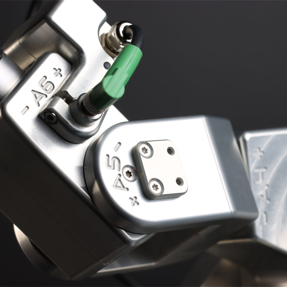 (a) upper fixture on link 4
 (b) lower fixture on link 4
Figure 33 The cable management option (CMFM) for the Meca500 robot arm consists of two fixtures attached to the body of the robot arm, each having a pair of threaded holes.#
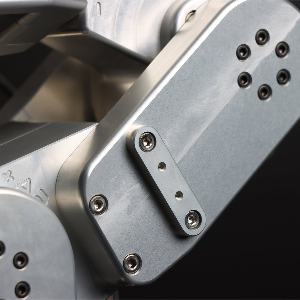
Figure 34 presents the specifications of the threaded holes on each fixture.


Figure 34 Specifications of CMFM threaded holes#
Finally, Figure 35 shows an example of cable routing using the CMFM.
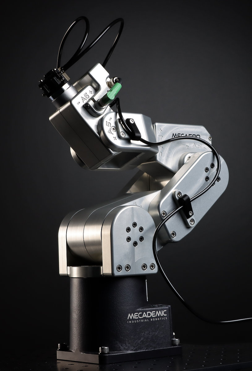
Figure 35 An example of cable routing using the CMFM option#
If you purchase the CMFM option at the same time as your Meca500, the fixtures come pre-installed on the robot arm. However, you can order the CMFM option separately and install it yourself by following these step shown in this installation video.