6. Installing an end-effector#
You can install end-of-arm tooling (EOAT) on the MCS500 and control it via the optional MVK01 I/O and vacuum module or directly from your PLC.
The MCS500 can be mounted table-top or upside-down. For that purpose, the two ends of the spline shaft are identical and symmetric. Each of these two ends is called the mechanical interface and should be used for fixing EOAT. The dimensions of the mechanical interface are shown in Figure 30.


Figure 30 The mechanical interface of the MCS500#
Note that we also offer a special hollow-shaft version of our MCS500. The only difference is that a Ø3 opening runs through the entire shaft and that the threaded holes at both ends are M5X0.8 instead of M3X0.5. The dimensions of the mechanical interface for the hollow-shaft version are shown in Figure 31.


Figure 31 The mechanical interface of the MCS500-HS (hollow shaft special version)#
The FRF (Flange Reference Frame) is fixed to the end of the spline shaft that is closer to the robot’s base, so that its z axis coincides with the axis of the spline shaft and points away from the robot’s base, its origin (called the flange center point, or FCP) is at the very end of the spline shaft, and its x axis is perpendicular to the plane of the Weldon flat, as shown in Figure 32.
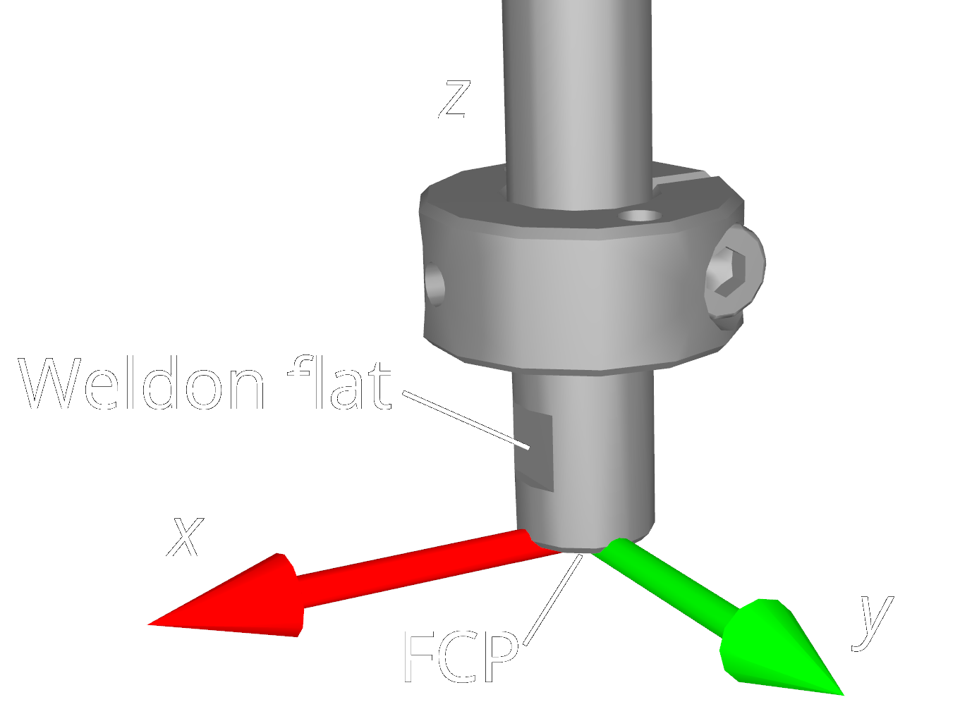
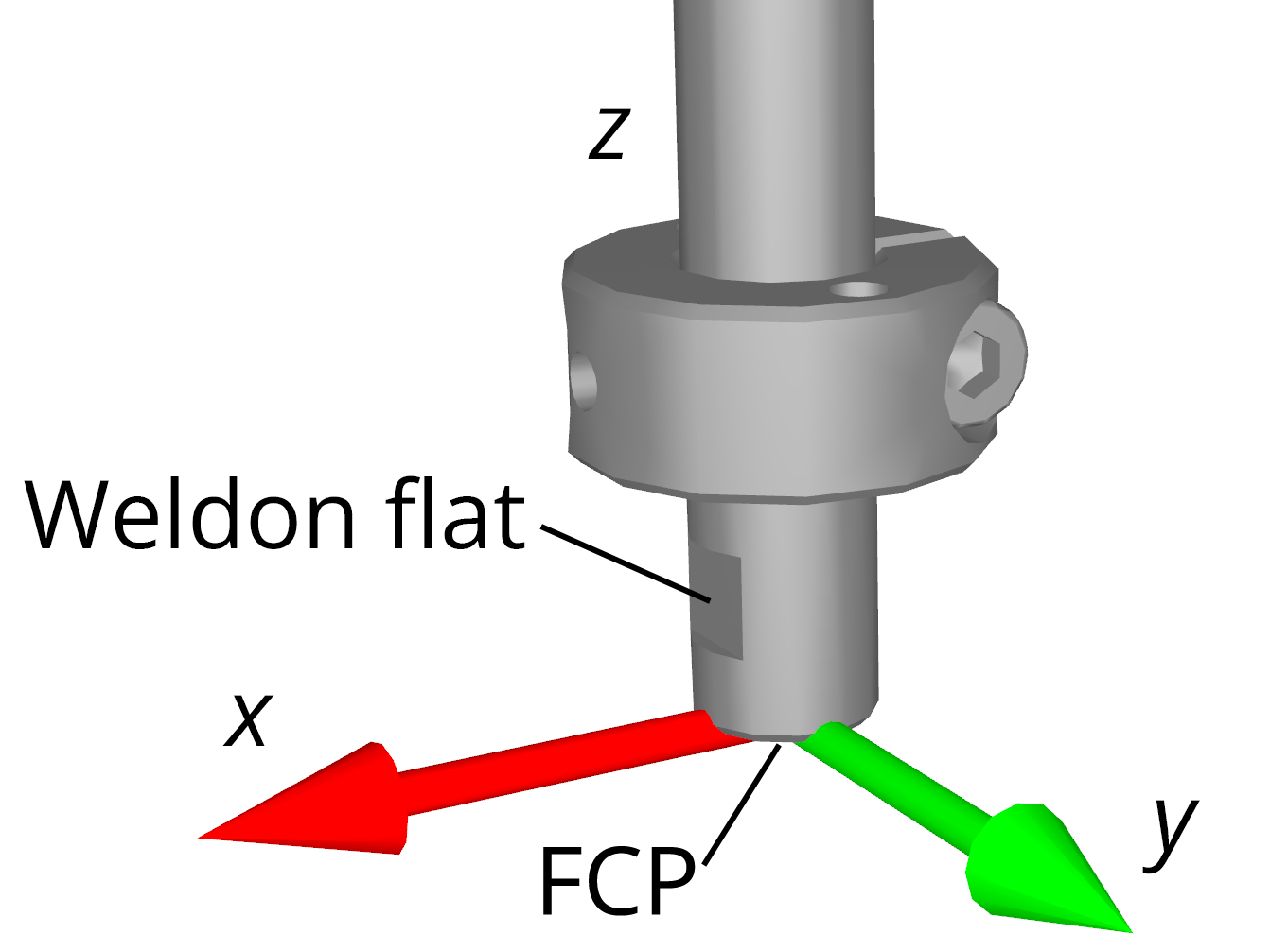
Figure 32 Placement of the FRF (always on the end closer to the robot base)#
Danger
Keep the robot unpowered while installing/removing EOAT to its mechanical interface.
Do not exceed the robot payload.
Securely fasten the EOAT to the mechanical interface using M3 screws and a set screw applied against the Weldon flat.
Warning
Never remove either of the retaining rings from the spline shaft — doing so will cause permanent damage to the ball-screw spline assembly.
Do not over-tighten the M3 screws. Use a torque of 1.5 Nm.
Securely fasten the EOAT to the mechanical interface using a set screw applied against the Weldon flat. For added safety, especially with heavier payloads, use M3 screws to attach your EOAT to the retaining ring.
For the standard MCS500, we also offer an optional suction cup holder (MCS500-TA01) for light loads, which can be easily mounted using a set screw, as shown in Figure 33. (The suction cup does not come with the holder.)
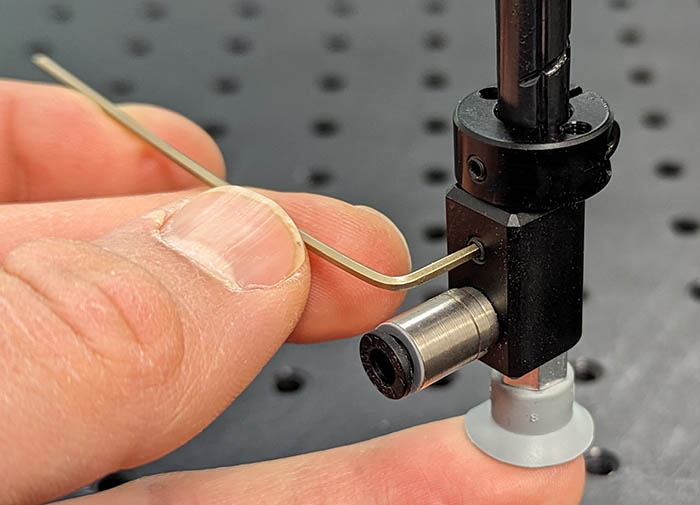 (a) Installing the suction cup holder
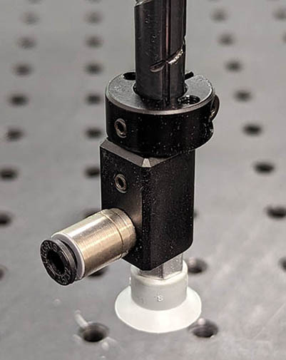 (b) Suction cup fully installed
Figure 33 Installing the optional suction cup holder (MCS500-TA01)#
The dimensions of the optional suction cup holder are shown in Figure 34. You can also download the CAD file of the holder from here.


Figure 34 Main dimensions of the optional suction cup holder#
Finally, cables or tubing from the end-effector can be rerouted to the base by attaching them onto the arch-shaped cable conduit of the robot, using the two M3 threaded holes shown in Figure 35.


Figure 35 Placement of the threaded holes on the cable conduit of the robot#