5. Operating the robot system#
This section presents the basic procedures for setting up and operating the MCS500 robot system. For further details, refer to the MecaPortal Operating Manual (MC-OM-MCS500), which describes the web interface of the robot, and to the Programming Manual (MC-PM-MCS500).
5.1. First-time use (not applicable to the PS200NB)#
Danger
For prototyping purposes, the MCS500 comes with its own dual DB15 dongle (recall Section 2.3.3). NEVER CONNECT THE DONGLE OF A MECA500 TO THE MSIPS MODULE OF THE MCS500, OR ELSE YOU WILL DAMAGE THE MCS500.
Danger
To start using the MCS500, plug the dual D-Sub dongle, while the MSIPS module is unpowered. Once you have become acquainted with the MCS500 and performed your risk assessment, remove the dongle and wire your safety I/O connections (see Section 2.3.2).
Danger
When using the dual DB15 dongle, you cannot use the robot in manual mode. (This is because the enabling device signal must be removed upon entering the manual mode). Therefore, you must take extra precautions and keep the robot in a safety enclosure.
5.1.1. Configuring your Ethernet connection (first time use)#
Configure your computer Ethernet connection with a static IP address, on the same subnet as the robot’s default IP address: 192.168.0.100. The way to do this differs from one operating system to another. The figure below shows how to do this in Windows and in Linux.
Note
The default IP address of the robot is 192.168.0.100.
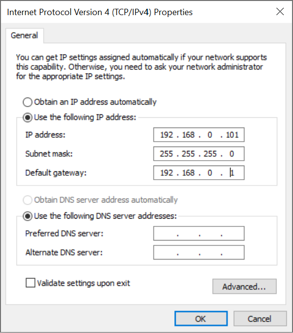 (a) Windows
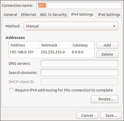 (b) Linux
Figure 18 Two examples of how to configure the IP address of your computer#
5.2. Power-up procedure#
5.2.1. Powering the robot#
Turn the MSIPS module on. The green LED on the module (next to “Power”) will be illuminated. The robot’s LEDs will start flashing for about twenty seconds while the robot’s controller is booting. Once the controller is ready, the three small LEDs on the robot’s base will stop flashing, unless there is a stop condition.
Make sure that all stop signals are removed and the three small LEDs on the robot’s base has stopped flashing (after about twenty seconds), and the Status LED on the MSIPS module is blinking.
Change the operating mode to manual or automatic mode with the physical switch key.
Now, you must provide power to the robot motors by briefly activating the Reset function (e.g., by pressing the RESET button on the MSIPS module). Before you do so, make sure the E-Stop function is deactivated and that all safety conditions are satisfied. You will hear a clicking sound and the big yellow LED on the robot’s base will light up. It will start blinking, once all safety conditions are satisfied and reset is possible.
5.2.2. Connecting to the robot#
Open (preferably) the latest version of Google Chrome and type MCS500’s default IP address 192.168.0.100 in the address bar.
MCS500’s web interface, called MecaPortal, should load instantaneously (see figure below). The MecaPortal is described in detail in a separate manual (MC-OM-MCS500).
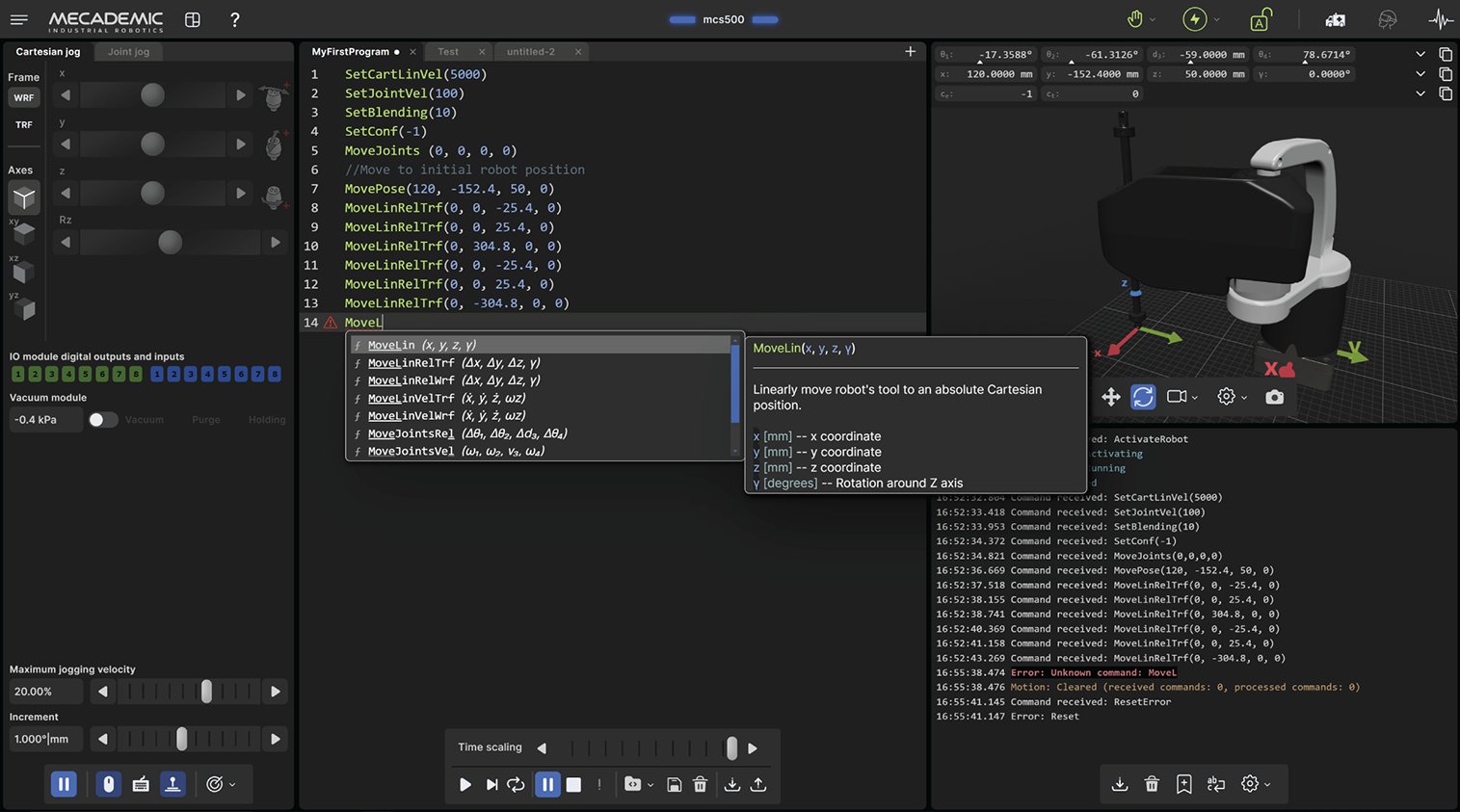
Figure 19 Overview of the MecaPortal#
5.2.3. Changing the robot’s network configuration (optional)#
Click on the connection state button on the top right of the MecaPortal and select
 “Control” (see figure below).
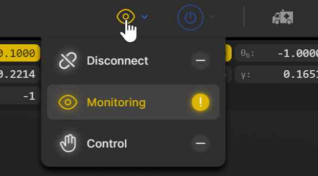
Figure 20 Connection state button#
Click on the configuration menu button,
 , in the top left corner of the
MecaPortal and select “Network configuration”.
, in the top left corner of the
MecaPortal and select “Network configuration”.Depending on your configuration, activate the toggle DHCP to automatically receive an address from your router or leave untoggled to force a specific IP. You don’t need to reboot the robot; the new configuration will be applied as soon as you click on the Apply button (see figure below).
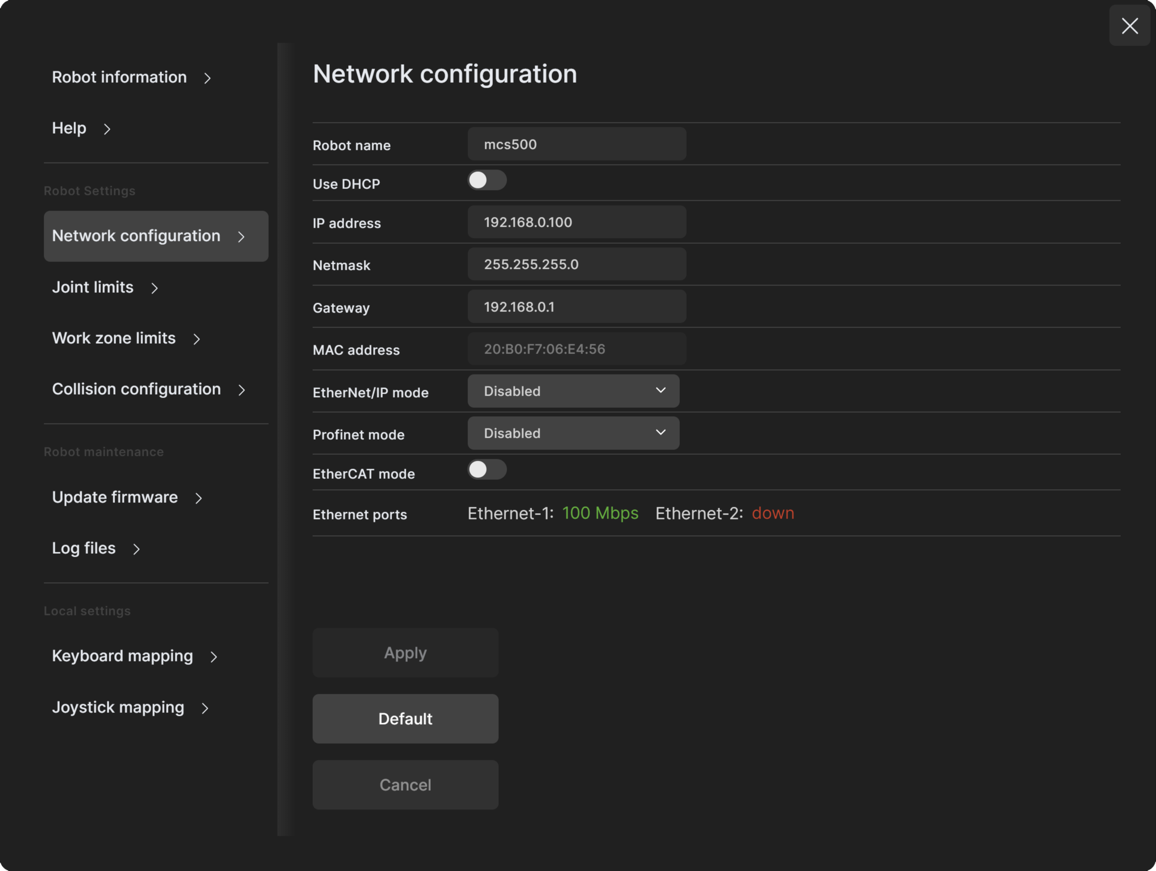
Figure 21 Changing the robot’s network configuration#
5.2.4. Resetting the operation mode#
After an operation mode change, the robot immediately decelerates to a complete stop, and power is removed from the robot motors. Depending on the new operation mode, the following actions should be performed before using the robot:
Locked: In locked mode, you cannot power the robot motors, but you can do everything that can be done while the robot is deactivated (e.g., use it in simulation mode, change settings, etc.).
Manual: In manual mode, you need to first press your enabling device halfway, then press the Reset button, then click on
 to activate the robot, which
will power the motors. As soon as you release the enabling device, the robot
decelerates to a complete stop. At that time, if no other safety stop signal is
present (the P-Stop 1 and P-Stop 2 signals are muted only while the enabling device
signal is active), the robot is simply put in pause mode. To resume using your robot,
press the enabling device again, and then click on “ResumeMotion” in the red banner
that will appear in the MecaPortal. If a P-Stop 1 signal was present upon releasing
the enabling device, then you would need to remove the signal, press the Reset button,
and then activate the robot.
to activate the robot, which
will power the motors. As soon as you release the enabling device, the robot
decelerates to a complete stop. At that time, if no other safety stop signal is
present (the P-Stop 1 and P-Stop 2 signals are muted only while the enabling device
signal is active), the robot is simply put in pause mode. To resume using your robot,
press the enabling device again, and then click on “ResumeMotion” in the red banner
that will appear in the MecaPortal. If a P-Stop 1 signal was present upon releasing
the enabling device, then you would need to remove the signal, press the Reset button,
and then activate the robot.Automatic: In automatic mode, you only need to press the Reset button in order to power the motors.
5.2.5. Activating the robot#
Once the motors are powered, click the  button in the menu bar and
select “Activate”. This starts the motors control and disengages the
brakes.
button in the menu bar and
select “Activate”. This starts the motors control and disengages the
brakes.
5.2.6. Moving the robot#
After activating the robot, click the  button in the jogging panel and select
“Zero all joints”. The robot will move all of its joints to their zero positions. In
this robot joint set (shown in Figure 1), the robot is in a
so-called singularity. Most industrial robots cannot move in Cartesian mode from such a
singularity. In order to simplify the use our robots, we have implemented an algorithm
that allows them robot to move through such a singularity.
button in the jogging panel and select
“Zero all joints”. The robot will move all of its joints to their zero positions. In
this robot joint set (shown in Figure 1), the robot is in a
so-called singularity. Most industrial robots cannot move in Cartesian mode from such a
singularity. In order to simplify the use our robots, we have implemented an algorithm
that allows them robot to move through such a singularity.
Note
The Cartesian coordinates displayed above the robot in the web interface are those of the Tool Reference Frame (TRF) with respect to the World Reference Frame (WRF). Both frames are displayed in the web interface. By default, the TRF is located at the mechanical interface of the robot and the WRF at the bottom of the robot’s base. The origin of the TRF is called the TCP (Tool Center Point).
Note
In the MCS500, the z-axis of all reference frames point “upwards” (relative to a table-top installation), so we use only one angle, γ (gamma), to define the orientation of one reference frame with respect to another.
Thus, for example, you can simply go to the Cartesian tab of the jogging menu, and with the TRF option selected, press the right arrow button of the x jogging bar. Alternatively, you can perform a joint motion by following these steps:
Clear the programming text field, type MoveJoints(-45,45,-80,0), and press
 .
.
The following figure shows the resulting robot position.
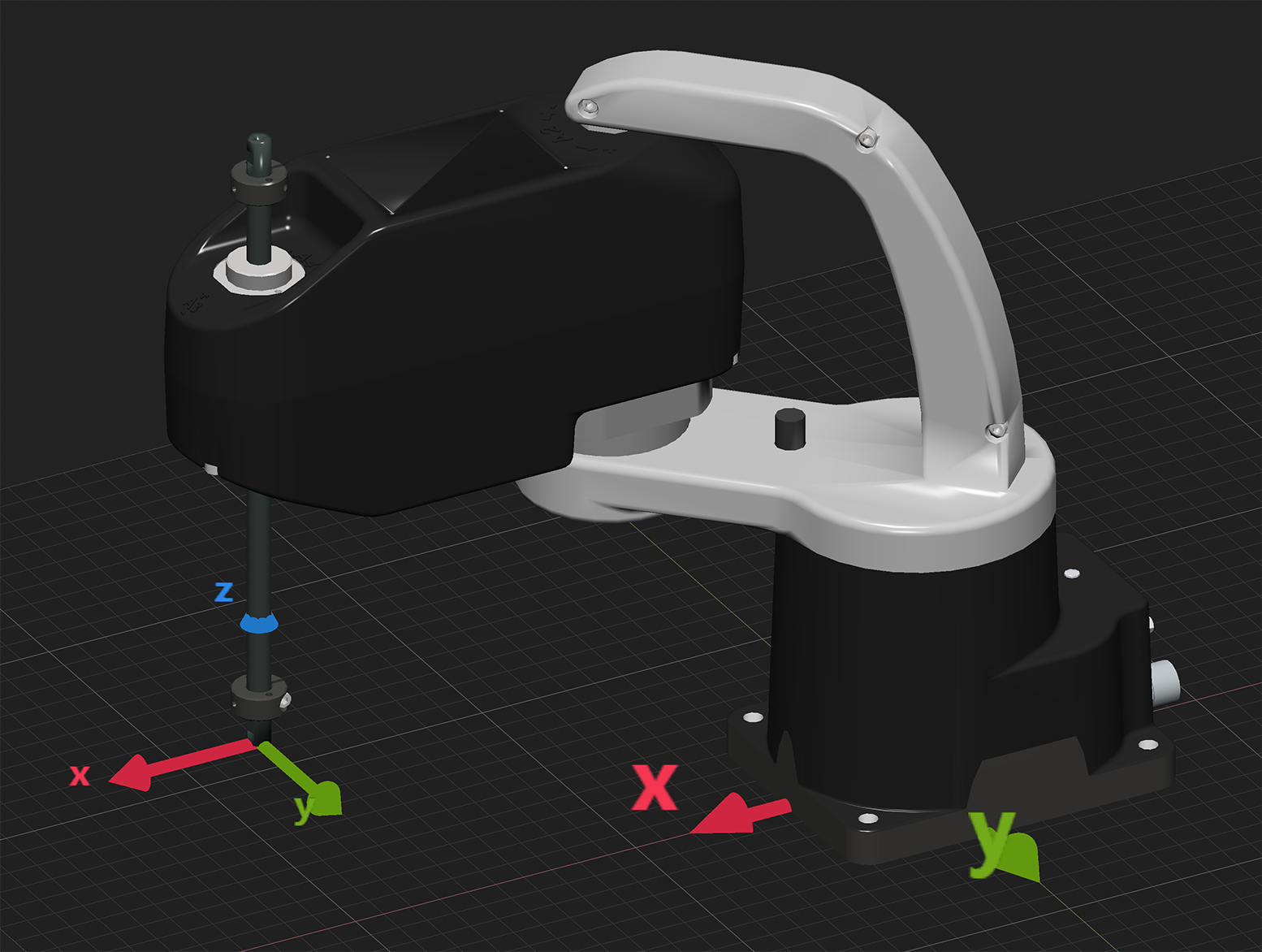
Figure 22 Robot position for MoveJoints(-45,45,-80,0)#
5.3. Power-off procedure#
5.3.1. Zeroing the robot joints (optional)#
It might be a good idea to always bring the robot joints to their zero positions before turning the robot off. This can be done in two ways:
send a MoveJoints command with all four arguments equal to 0
OR
click the
 button in the jogging panel and select “Zero all joints”.
5.3.2. Deactivating the robot#
To deactivate the robot
click the
button and then select “Deactivate”
OR
send the DeactivateRobot command via the programming editor.
Note
If you accidentally close your web interface before deactivating the robot, the robot will stop (in case it was moving) but will remain activated.
5.3.3. Disconnecting the robot#
To disconnect the web interface from the robot, select the  option
from the connection state group.
option
from the connection state group.
Danger
If you disconnect the web interface from the robot before deactivating the robot, the robot will stop moving.
5.3.4. Removing power#
Finally, switch the MSIPS module off.
Warning
Never detach the DC power connector from the robot’s base, before switching the MSIPS module off or unplugging the module’s AC power cord from the AC outlet.
5.4. Robot’s base#
A series of LEDs are located at the rear of the robot’s base (see Figure 23). The meanings of these LEDs will be summarized in what follows.
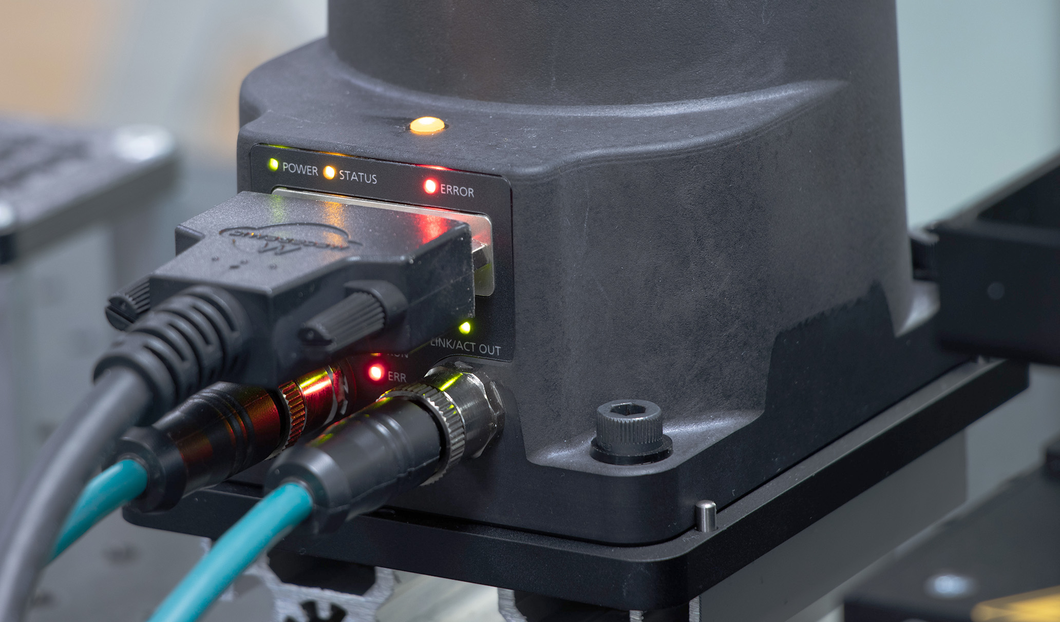
Figure 23 Robot’s base#
5.4.1. LEDs#
After a power up, the Power, Status and Error LEDs will flash fast simultaneously during a couple of seconds. After that, the LEDs will be lit as described below.
Power, Status, and Error LEDs
The Power, Status, and Error LEDs are used to indicate various operating situations, as detailed in Table 10. Additional sequences occur during network and factory resets, as detailed in Section 9.
Situation |
Power (green) |
Status (yellow) |
Error (red) |
|---|---|---|---|
Robot not powered |
off |
– |
– |
Robot powered (motors may be off) |
on |
– |
– |
Fatal MSIPS error |
fast blink (0.1 s on, 0.1 s off) |
– |
– |
Robot cannot be activated (safe boot) |
– |
off |
– |
Robot can be activated |
– |
slow blink (0.5 s on, 0.5 s off) |
– |
Robot activated |
– |
on |
– |
No error or protective/emergency stop |
– |
– |
off |
Robot in error state |
– |
– |
on |
P-Stop 2 activated |
– |
– |
1 flash per second |
P-Stop 1 activated |
– |
– |
2 flashes per second |
E-Stop activated |
– |
– |
3 flashes per second |
Booting |
slow blink (all three LEDs blink simultaneously once every second) |
||
Booting in Safe mode (firmware update) |
quick blink (all three LEDs blink simultaneously once per 0.2 s) |
||
Updating the firmware |
quick traveling blink (each LED blinks quickly in sequence, once every second) |
||
Motors ON LED
The large yellow LED on the top of the robot’s base is on when the motors are powered and off when power is removed from the motors (e.g., after an E-stop or when the switch key is in Locked operating mode position). Note that the light will also light up temporarily if you are moving manually the robot joints 1 or 2 (due to the induced current in the motors).
Link/Act IN and Link/Act Out LEDs
Both LEDs are green and flash when there is network activity in the corresponding Ethernet port. The LEDs function in the same manner as on a normal Ethernet RJ-45 port.
Run LED
This green LED is used only when the robot is controlled via EtherCAT (see the Programming Manual).
ERR LED
This red LED is used only when the robot is controlled via EtherCAT (see the Programming Manual).
5.5. MSIPS module#
5.5.1. Emergency and protective stops#
Once you power up the robot, you must make sure all safety stops are disengaged. Then, pressing the RESET button (or enabling the RESET input) sends power to the robot motors.
Once the robot is activated, pressing an E-Stop at any time instantly sends a signal to the robot to rapidly decelerate and come to a complete stop. The MSIPS module then waits for a signal from the robot indicating that the robot is completely stopped, and as soon as that signal is received, but no later than in 500 ms, the MSIPS module completely cuts power to the robot motors. The robot brakes are then automatically applied to the spline shaft (i.e., to joints 3 and 4). To use the robot again, you must remove all stops signals, and press Reset, then activate the robot.
5.5.2. LEDs on the MSIPS module#
The MSIPS module is also equipped with three LEDs. Their description is presented in Table 11.
Situation |
Power (green) |
Status (yellow) |
Error (red) |
|
|---|---|---|---|---|
MSIPS module is switched off. |
off |
– |
– |
|
A fatal error detected (e.g., invalid voltage or safety input mismatch). |
fast blink (0.1 s on, 0.1 s off) |
– |
on |
|
Reset button pressed for too long, redundant signal mismatch detected, monitored standstill not respected, voltage fluctuation detected, or internal minor software error detected. |
– |
– |
on |
|
The MSIPS module is turned on. |
on |
– |
– |
|
The robot motors are not powered and a RESET is not allowed. |
– |
off |
– |
|
The robot motors are not powered but a RESET is allowed. |
– |
slow blink (0.5 s on, 0.5 s off) |
– |
|
The robot motors are powered. |
– |
on |
– |
|
There is no error or a stop signal. |
– |
– |
off |
|
P-Stop 2 is activated. |
– |
– |
1 flash per second |
|
P-Stop 1 is activated. |
– |
– |
2 flashes per second |
|
E-Stop is activated. |
– |
– |
3 flashes per second |
|
Operation mode changed or enabling device released in manual mode. |
– |
– |
slow blink |
|
Upgrading the firmware |
all LEDs flash sequentially |
|||
Booting |
all LEDs are slowly blinking simultaneously |
|||
Shutdown |
all LEDs are on for about 7 seconds |
|||