2. Safety#
The MCS500 weighs less than 5 kg, but it can move very fast and cause injuries, especially when certain end-effectors are attached to its flange (e.g., a sharp tool).
Note
We designed this robot with the principles of ISO 10218-1 in mind. However, the robot is not fully compliant with this standard and has not been certified by an independent third party. This limitation does not affect normal operation when the robot is properly integrated into a safeguarded system.
2.1. Fundamental safety information#
2.1.1. Safety symbols and signal words#
The following are the three types of safety indicators used in this manual. Each is visually distinguished by a specific color, an icon, and a signal word to convey certain information.
Note
Identifies information that requires special consideration.
Warning
Provides indications that must be respected in order to avoid equipment or work (data) on the system being damaged or lost.
Danger
Provides indications that must be respected in order to avoid a potentially hazardous situation, which could result in injury.
The following table lists the safety labels and engravings on the robot arm and MSIPS module, respectively.
Symbol |
Description |
|---|---|
Read the user manual carefully before operating the robot system. |
|
Pinch point hazard — Keep hands and fingers away. |
|
Crush hazard — Stay clear of reciprocating spline shaft and robot’s distal link. |
|
Electric shock hazard — Do not disassemble. |
|
Hot surface — Do not touch for extended periods. |
|

|
Sensitive material beneath — Do apply pressure on plate. |

|
Electrostatic sensitive device — Do not touch connectors. |
2.1.2. Required personnel qualifications#
Only trained and qualified personnel who have read and understood this manual are permitted to install, operate, maintain, or decommission the MCS500 robot system. Personnel must be familiar with applicable safety standards and should have received appropriate training in industrial robot safety procedures.
2.1.3. Intended use#
Use the MCS500 robot system only in industrial settings for handling an end-effector. For the required operating conditions, see the remainder of this user manual.
2.1.4. Risk assessment#
Conduct a risk assessment to satisfy legal obligations. Because the MCS500 is partly completed machinery, its safe operation depends on how it is integrated into the overall system. A qualified third-party integrator or the user acting as integrator must evaluate the hazards of the entire robot cell, including the MCS500, its end effector, and all adjacent equipment. We recommend following the guidelines of ISO 12100:2010 and ISO 10218-2:2025 when conducting and documenting this assessment.
2.1.5. Limitation of liability#
Mecademic assumes no responsibility for injuries or damages resulting from improper installation, operation, maintenance, or unauthorized modification of the MCS500 robot system.
This manual provides comprehensive safety guidelines specific to the MCS500, but does not cover the design, installation, or operation of the complete robot application or peripheral equipment that may affect system safety. System integrators are responsible for ensuring that the complete robot application complies with all applicable laws, standards, and regulations in the relevant jurisdiction and for identifying and mitigating any significant hazards.
Even when all instructions in this manual are followed, residual risks may remain. Mecademic cannot be held liable for any resulting harm or property damage.
2.1.6. Residual risks#
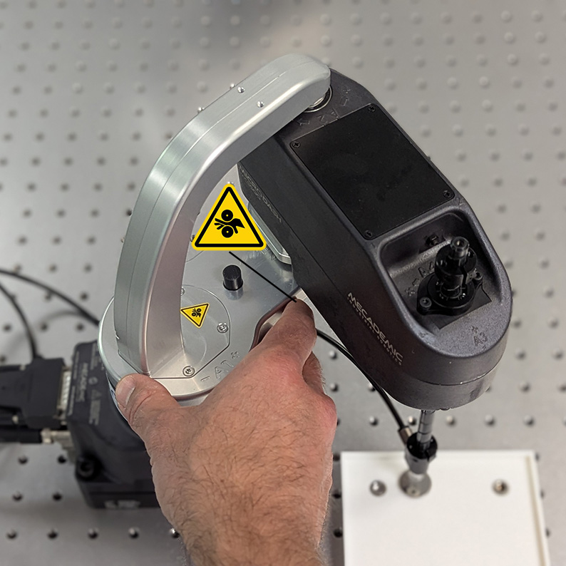
Despite full compliance with installation guidelines and protective measures, certain residual hazards remain — especially during manual interventions or whenever a safety system is overridden:
pinching of fingers or hands (Figure 5a);
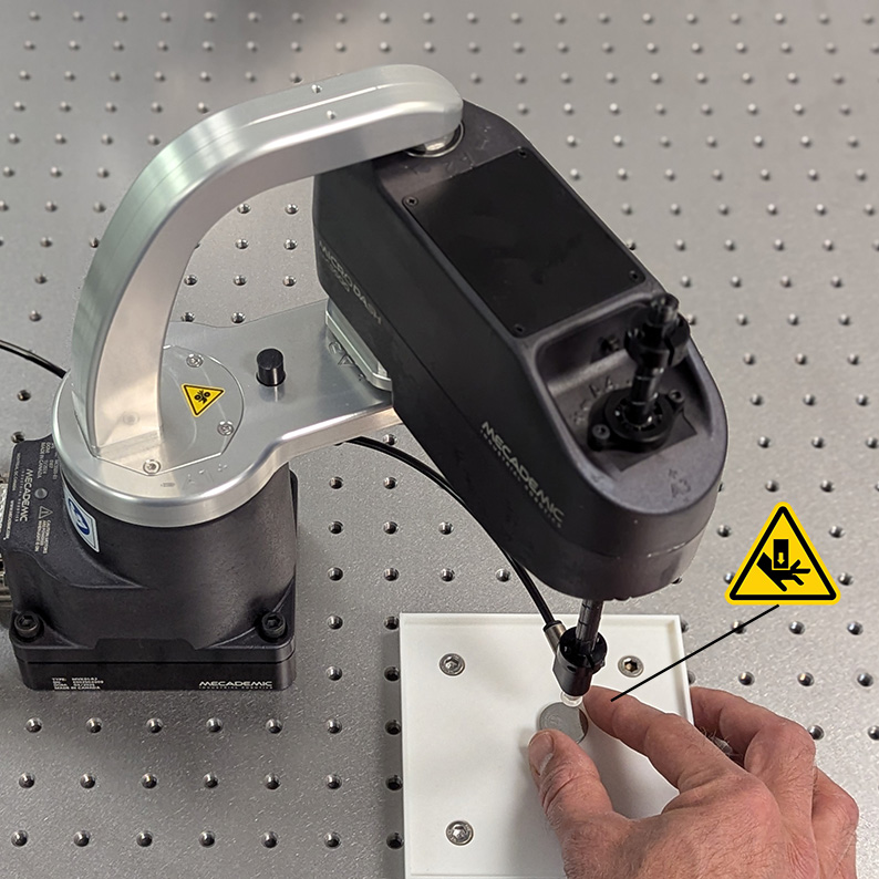
crushing or pinning of fingers or hands (e.g., Figure 5b);
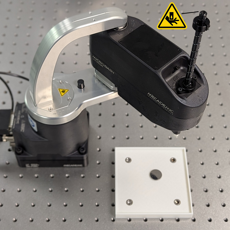
impact on body parts (e.g., Figure 5c).
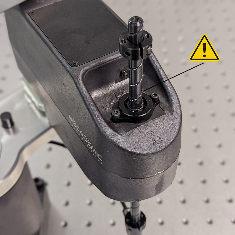
entanglement of loose clothing or long hair in moving parts (e.g., Figure 5d);
The risk of sustained pinning or pinching is low because the robot joints are easily back-driven (overpowered), allowing an operator to push the arm away.
 (a)
(a)
 (b)
(b)
 (c)
(c)
 (d)
(d)
Figure 5 Examples of residual risks: (a) pinching between proximal and distal link; (b) pinning between end-effector and fixed objects; (c) impact between spline shaft tip and body part such as head of hand; (d) entanglement of long hair or loose clothing with spline shaft.#
2.1.7. General safety guidelines#
Before removing the robot from its shipping box, you must familiarize yourself with the following general safety guidelines.
Danger
When the robot arm is fully folded, it can be temporarily deposited on its base, as shown in Figure 6a. In other robot positions (e.g., Figure 6b), the robot will tip and should not be placed on its base without fixing it. If the robot tips and falls from a height, it may cause an injury, and certainly get damaged.
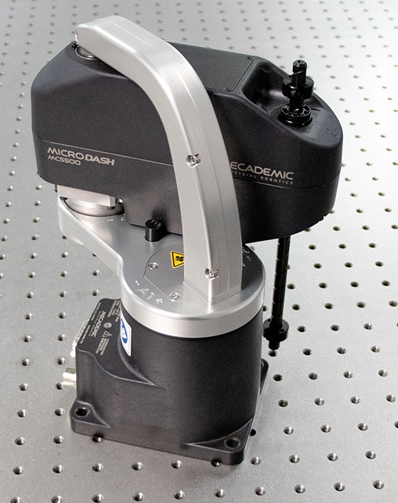 (a) correct
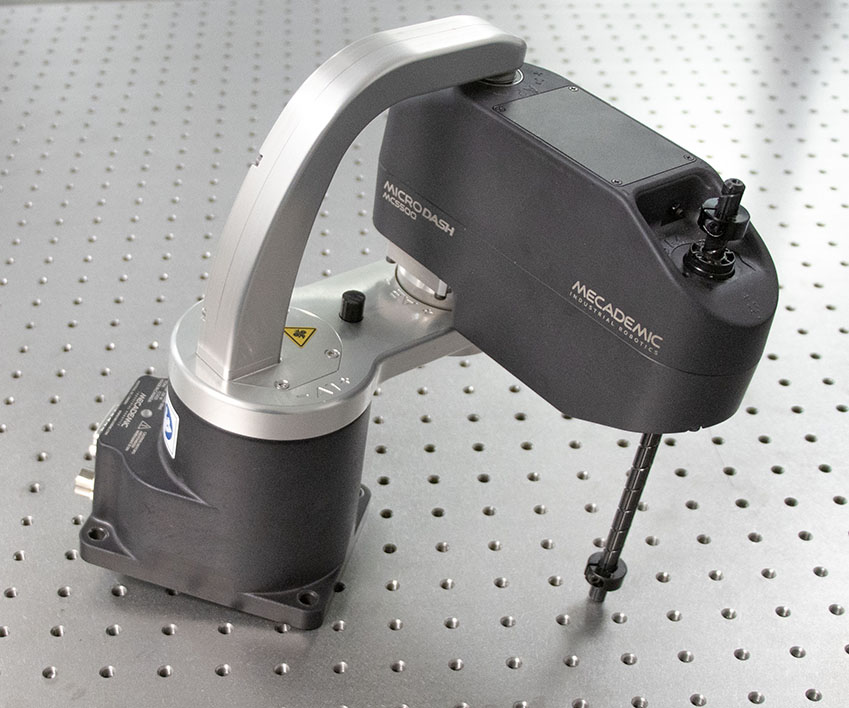 (b) NOT correct
Figure 6 You may temporarily place the MCS500 on its base, but only if the robot arm is fully folded.#
Danger
Ensure the robot arm and end of arm tooling are securely fastened.
Do not modify or disassemble the robot arm or the MSIPS module.
Do not touch the MSIPS module for extended periods, while in operation.
Keep your head and hands away from the robot arm and its reciprocating spline shaft.
Ensure all clothing fits closely and remove jewelry before operating the robot. Secure long hair away from any moving parts.
Wear protective gloves and/or safety glasses when required for specific end-of-arm tooling and manipulated objects.
Warning
Handle the robot with care.
Do not force the brakes on the robot’s spline shaft, unless there is an emergency!
Never unscrew the retaining rings on the spline shaft.
Inspect the robot and the MSIPS module for damages. If either appears damaged, do not use them and contact us immediately.
Do not apply pressure to the cover plate on the bottom of the robot’s base.
Do not place any labels on the bottom of the robot’s base.
Do not touch the connectors at the bottom of the robot’s base.
Do not use or store the MCS500 in a humid environment.
Do not expose the robot to strong magnetic fields.
Do not operate the MCS500 at temperatures below 5°C or above 45°C.
Use only the MSIPS module provided with your system.
Use only the Ethernet and DC-power cables provided. If you need a longer Ethernet cable, contact us.
Fix solidly the base of the robot using four M6 screws, tightened at 3 Nm.
2.2. Safety-related functions and operating modes#
The MSIPS module features built-in safety functions and provides safety I/O digital control signals via two ports on the MSIPS module for connection to PLCs and protective devices (Figure 7). All safety functions and I/O channels are designed in accordance with EN ISO 13849-1, using a Category 3 architecture to achieve Performance Level d (PL d).
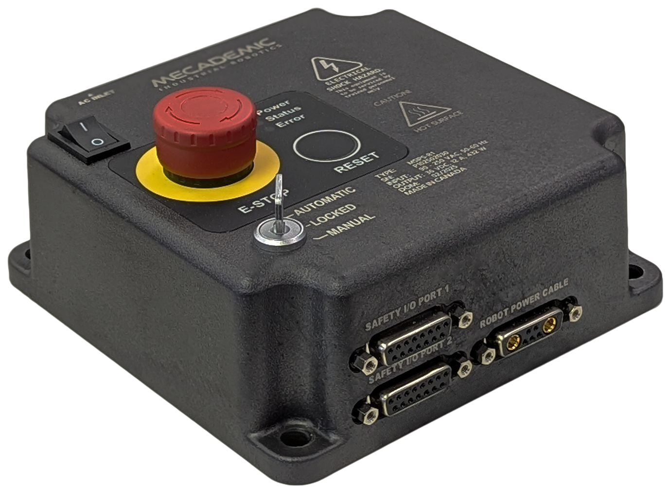
Figure 7 The MSIPS module#
2.2.1. Stop categories#
The robot can initiate three stop categories—as defined in IEC 60204-1—depending on the circumstances, as shown in Table 3.
Stop Category |
Description |
|---|---|
0 |
The robot stops immediately by cutting power to the motors. |
1 |
When initiated, the robot decelerates in a controlled manner to a full stop within 150 ms. Power is removed from the motors after 380 ms regardless of system state. During deceleration, the robot may deviate from its initial path. |
2 |
The robot decelerates to a full stop while maintaining its original path, with power remaining available to the motors. |
2.2.2. Safety functions#
The MCS500’s safety functions are listed in Table 4. For each function, the table indicates the robot operating mode in which it is active and the resulting stop category.
Trigger |
Description |
Oper. Mode |
Reaction |
|---|---|---|---|
E-Stop |
Emergency Stop |
Auto/Manual |
Stop Category 1 |
P-Stop 1 |
Protective Stop 1 |
Auto |
Stop Category 1 |
P-Stop 2 |
Protective Stop 2 |
Auto |
Stop Category 2 |
Monitored standstill |
Prevents robot from moving after a Stop Category 2 |
Auto/Manual |
Stop Category 0 |
Start interlock |
Prevents motors from getting power before required conditions are satisfied |
Auto/Manual |
Stop Category 1 |
Prevents motors from getting power |
Locked |
Stop Category 1 |
|
3P enabling |
Prevents robot from moving if the enabling device is not activated |
Manual |
Stop Category 2 |
Reduced speed |
Prevents robot from moving faster than 250 mm/s |
Manual |
Stop Category 1 |
The E-Stop function of the MCS500 meets the performance level required by ISO 10218-1:2025 (5.4.2) which is PL=d with a circuit structure of Category 3 based on ISO 13849-1:2023. As per ISO 10218-1:2025 (5.4.2), a Category 3 structure means that:
A single fault in any subcomponent does not lead to the loss of the safety functions.
The single fault shall be detected at or before the next demand upon the safety function.
When the single fault occurs, the safety function is always performed and a safe state shall be maintained until the detected fault is corrected.
Safety equipment connected to the Protective Stop 1 function must meet the same requirements (PL=d and Category 3).
The E-Stop and the P-Stop 1 functions on the MCS500 are Stop Category 1, as per ISO 13850:2015 (4.1.4).
The E-Stop and the P-Stop 1 inputs are redundant with two separate channels and monitoring circuitry is used to ensure that no tampering is possible. This means the inputs must switch states in tandem within 50 ms otherwise a Stop Category 0 will occur (power is removed from the motors).
2.2.3. Robot operating modes#
The physical key switch on the MSIPS module (Figure 7) is the only way to select the robot’s operating mode. This key-operated switch has three positions: (1) automatic mode, (2) locked mode (motors off), and (3) manual mode.
Automatic mode
Automatic mode is a control state in which the robot executes programmed tasks without continuous operator intervention. In automatic mode, the robot can move at full speed, as long as all safety conditions are satisfied (i.e., the E-Stop function and the two protective stops must remain at logic high). In this mode, the three-position enabling device signal is ignored.
Locked mode
Locked mode is intended for preventing robot movements. In locked mode, power from the motors is removed and the brakes are engaged. In this mode, you can still change settings and save programs.
Manual mode
Manual mode is a control state intended for programming, testing, and fine-tuning robot motions. In manual mode, the robot can move at a limited speed as long as you keep the enabling device engaged (i.e., pressed to the midpoint position). Specifically, the linear speed of the TCP (the origin of the tool reference frame, set with the SetTRF command) is limited to 250 mm/s, and the angular speed of the TRF is limited to 500 °/s. In manual mode, as long as you keep the enabling device pressed halfway, the protective stop signals are muted (ignored).
2.3. E-Stop button and safety I/O connections#
2.3.2. Safety I/O connections#
After performing a risk assessment for your installation, you must design and connect the appropriate safety circuit to the two safety I/O DB15 ports on the MSIPS module (Figure 7). At minimum, you must supply a third-party power supply and a three-position enabling device, and you must wire both the enabling device and the internal E-Stop. Figure 8 shows the pinout of the DB15 connectors. The following explains the different connections:
E-Stop Button, four pins. These are the four terminals of the E-Stop button on the MSIPS module. The four pins of the E-Stop button MUST BE WIRED to the circuitry of the E-Stop Function, along with other external E-Stops (if necessary). Otherwise, the E-Stop button on the MSIPS module will not function.
E-Stop Function, four pins. This is the input that provides the E-Stop functionality to the robot.
Protective Stop Category 1 (P-Stop 1), four pins. This (redundant) safety input is intended for connecting optical curtains, or other presence-sensing safety devices.
Protective Stop Category 2 (P-Stop 2), four pins. This (redundant) safety input is used to stop the robot’s motion without removing power from the motors.
Reset, two pins. This input is for wiring an external reset button that will have the same functionality as the one on the MSIPS module.
Enabling Device, four pins. This is for connecting a three-position enabling device, necessary for operating the robot in manual mode.
Reset Ready, two pins. This output is enabled when the motors are ready to be powered (i.e., no safety stop is active) by activating the reset function.
Power Status, four pins. This (redundant) safety output indicates whether the robot motors are powered.


Figure 8 Pinout for the two DB15 connectors (Safety I/O ports)#
Danger
The E-Stop Function, Enabling Device, P-Stop 1 and P-Stop 2 are activated when the corresponding signal is logic low.
The Reset is activated when its signal is logic high.
The four pins of the E-Stop Button MUST BE WIRED to the circuitry of the E-Stop Function, along with other external E-Stops (if necessary). Otherwise, the E-Stop button will not work.
Warning
Beware that the two DB15 connectors are identical on the outside.
Warning
Do not use pins 8 from both DB15 connectors. These are for internal use only.
Note that the dimensions of the DB15 plug connectors must be at most 42 mm × 15.5 mm, as shown in Figure 9, or else they will interfere with each other or with the power cable. An example of a cable that meets all requirements is the CABLE-D-15SUB-M-OE-0,25-S from Phoenix Contact. That cable is shielded and has a DB15 plug connector on one side and single wires that are marked and fitted with ferrules on the other side, and can be ordered with a custom length. Off-the-shelf variants of the cable (in several lengths) are also offered.


Figure 9 Maximal feasible dimensions for the DB15 plug connectors#
The following two tables show further important details regarding the two connections of the two Safety I/O ports.
Warning
The safety outputs are designed to be connected to PLC inputs and not to control loads, especially inductive ones (e.g., a relay or a solenoid). There is no internal protection against the high voltage spike at the release of an inductive load.
Warning
Output signal switching device (OSSD) signals are not supported.
Pin |
Name |
Type |
Usage |
Notes |
|---|---|---|---|---|
3 |
Reset Ready – B |
Output |
The robot is ready for reset |
|
11 |
Reset ready – A |
|||
1 |
Power Status – B1 |
Output |
Robot motor power status |
|
9 |
Power Status 1 – A1 |
|||
2 |
Power Status 1 – B2 |
|||
10 |
Power Status – A2 |
|||
4 |
Enabling Device – B1 |
Input |
Enabling device signal for manual mode only |
|
12 |
Enabling Device – A1 |
|||
5 |
Enabling Device – B2 |
|||
13 |
Enabling Device – A2 |
|||
6 |
P-Stop 2 – B1 |
Input |
P-Stop 2 (hold) signal, muted in manual mode |
|
14 |
P-Stop 2 – A1 |
|||
7 |
P-Stop 2 – B2 |
|||
15 |
P-Stop 2 – A2 |
|||
8 |
DO NOT USE |
n/a |
n/a |
n/a |
Pin |
Name |
Type |
Usage |
Notes |
|---|---|---|---|---|
1 |
Reset – B |
Input |
External Reset Signal |
|
9 |
Reset – A |
|||
2 |
P-Stop 1 – B1 |
Input |
P-Stop 1 signal (e.g. fence), muted in manual mode |
|
10 |
P-Stop 1 – A1 |
|||
3 |
P-Stop 1 – B2 |
|||
11 |
P-Stop 1 – A2 |
|||
4 |
E-Stop Function – B1 |
Input |
E-Stop signal |
|
12 |
E-Stop Function – A1 |
|||
5 |
E-Stop Function – B2 |
|||
13 |
E-Stop Function – A2 |
|||
6 |
E-Stop Button – B1 |
Switch |
E-Stop button on MSIPS module |
|
14 |
E-Stop Button – A1 |
|||
7 |
E-Stop Button – B2 |
|||
15 |
E-Stop Button – A2 |
|||
8 |
DO NOT USE |
n/a |
n/a |
n/a |
In addition, the following figure shows the electric diagrams for the safety inputs and outputs, as well as for the E‑Stop button on the MSIPS module.
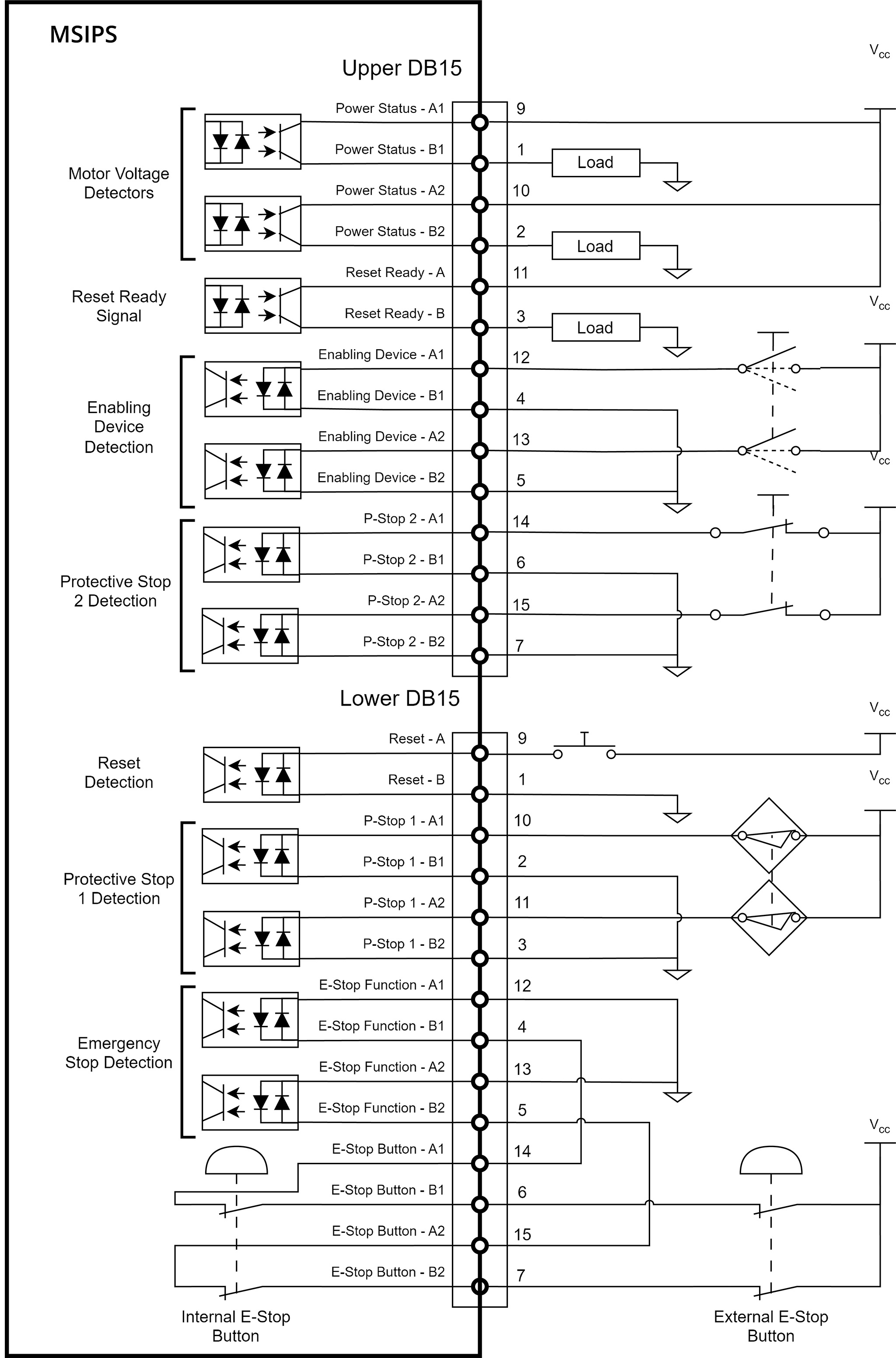
Figure 10 Electric diagram for the outputs, the inputs and the E-Stop button on the MSIPS module#
2.3.3. Dual D-Sub DB15 dongle (first time use and maintenance only)#
The provided dual D-Sub DB15 dongle can be used to temporary bypass safety connections as during first time use or during maintenance. Connect the dongle to the D‑Sub interface of the MSIPS module (Figure 11). This not only connects the internal E‑Stop button to the E‑Stop safety function but also completes the necessary wiring to satisfy the P‑Stop 1 and P‑Stop 2 safety functions.
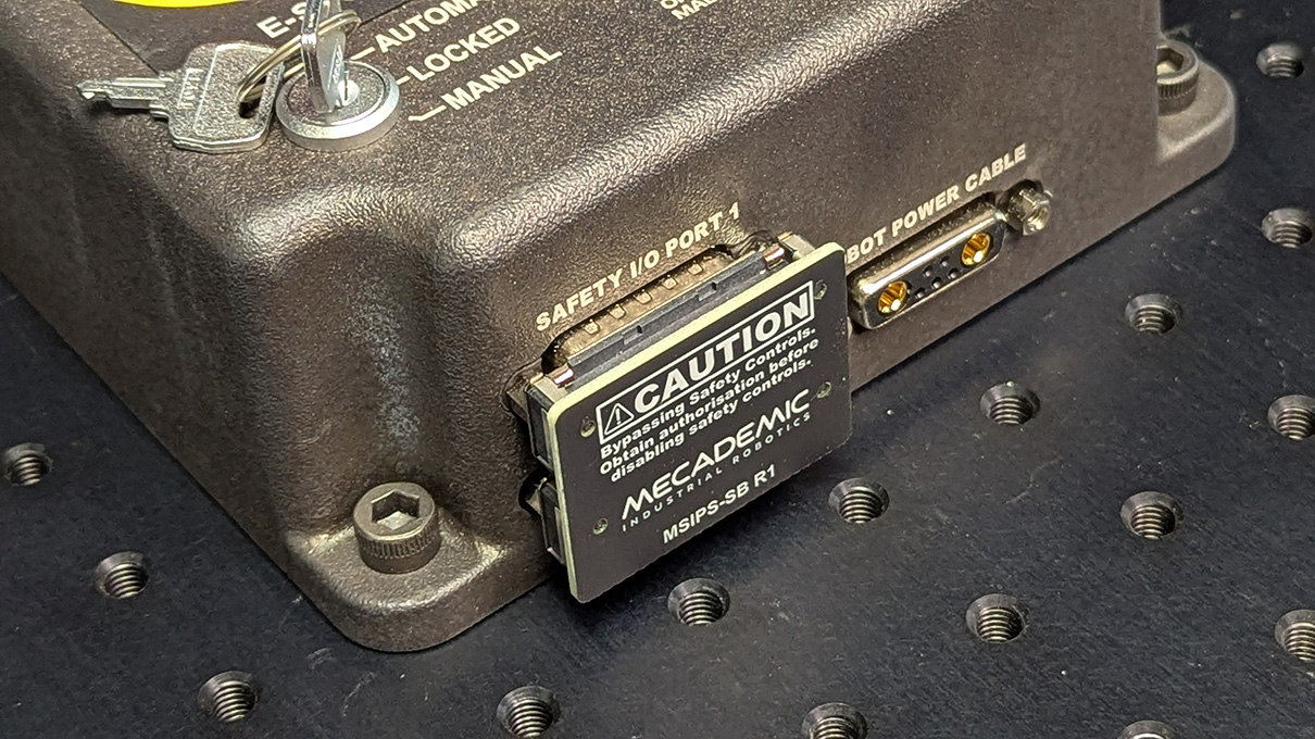
Figure 11 Dual D-Sub DB15 safety dongle installed#
Warning
Connect the dual DB15 dongle to the D-Sub interface of the MSIPS module, while the module is still switched off. NEVER CONNECT OR UNPLUG THE DONGLE WHILE THE MODULE IS ON.
Danger
The DB15 dongle is a bypass device for setup and maintenance only. Ensure proper safety I/O connections are wired when using the robot in production mode (see Section 2.3.2).
Danger
When using the dual DB15 dongle, you cannot use the robot in manual mode. (This is because the enabling device signal must be removed at least once upon entering the manual mode). Therefore, you must take extra precautions and keep the robot in a safety enclosure.
Danger
Stand away from the robot when it is activated, wear safety goggles and close-fitting clothing, keep long hair securely tied back and be attentive and alert. In case of an emergency, press the E-Stop button (on the MSIPS module) immediately.
2.4. Further safety information#
Recall Section 1.2 for a general description of the robot arm.
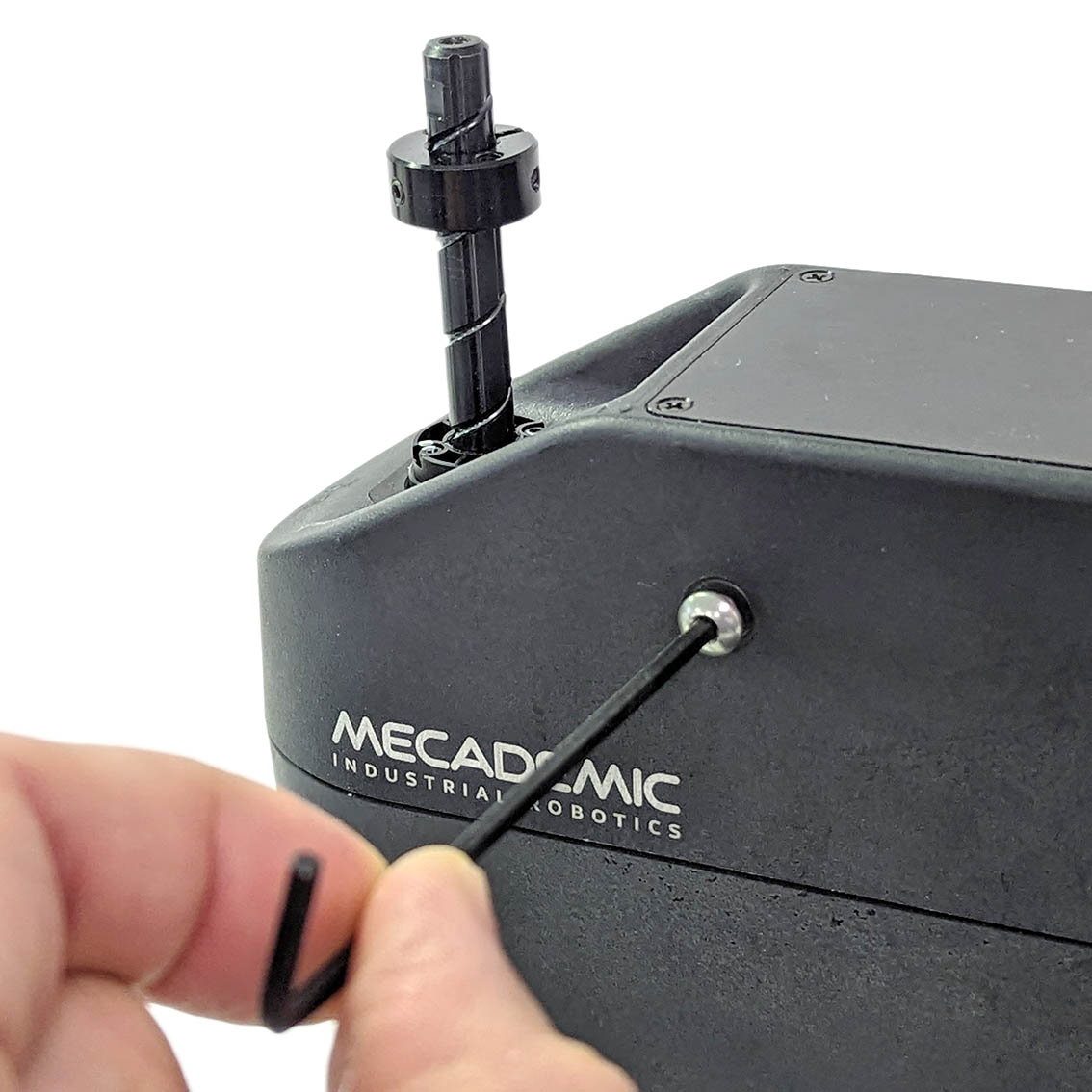
2.4.1. Brakes and limitations#
As already mentioned, the MCS500 is equipped with brakes at joints 3 and 4, i.e., at the spline shaft. These brakes can be disabled mechanically by removing the screw cap near the spline shaft, using a 2.5‑mm Allen key, and keeping the button inside the hole pressed, as shown in the figure below.
 (a) Remove the screw cap
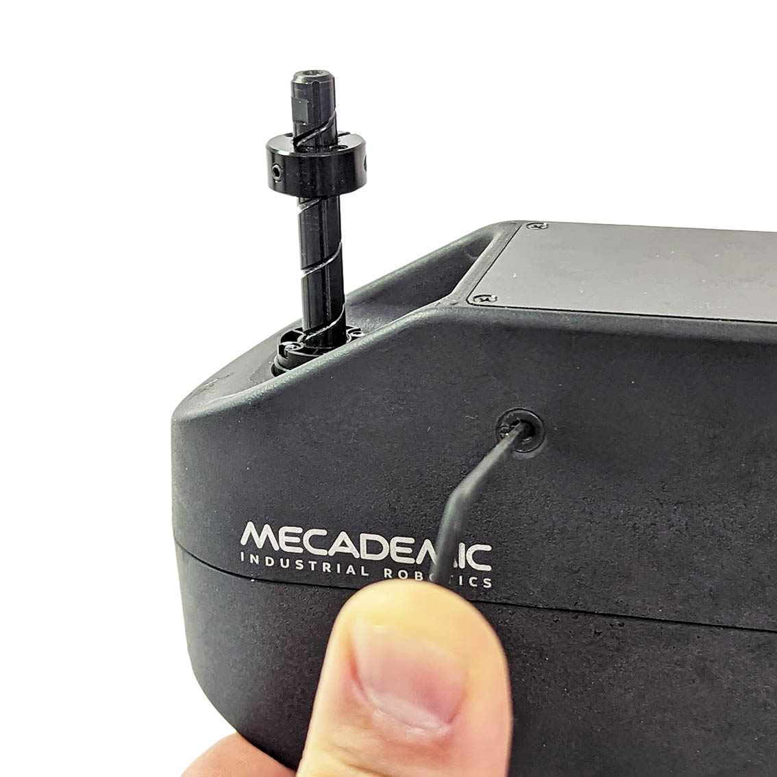 (b) Press the recessed button
Figure 12 Releasing mechanically the brakes on the spline shaft#
Danger
For safety reasons, release the brakes on joints 3 and 4 only when the robot is in locked mode or powered off.
When the brakes on the spline shaft are released, the shaft will not fall down, even if a 0.5 kg tool is attached to it. This is due to the friction in the assembly. You therefore need to apply external force to make the spline shaft move.
Warning
In case of an emergency, you can always overpower the brakes on the spline shaft. However, doing so frequently will damage the brakes.
Note
Note that in the case of a collision, the robot is not deactivated and you can easily reset the motion error and jog the robot away, without entering the safety enclosure of the robot. If you are worried about damaging your equipment, it is advisable to first enter recovery mode (as described in the Programming Manual).
2.4.2. Joint limits#
Because of the robot’s compact dimensions, mechanical means to limit joint range have not been incorporated. It is possible to design a fixture that can be attached to the robot’s base and that limits mechanically the range of joint 1. However, remember to not modify the robot itself (e.g., by removing screws from the robot).
The robot’s joint limits can be reduced by software means using the MecaPortal or the command SetJointLimits. The new software limits remain active even after power shutdown. However, they will be reset to the default values, if a factory reset is performed on the robot. These software limits are not safety rated.
Danger
Due to the extremely compact size of the robot, there are no provisions for adjustable hardware joint limits.
2.4.3. Joint torque limits#
Once a robot is activated and homed, you can also reduce the joint torque limits using the command SetTorqueLimits. However, the joint torque limits are reset to 100% each time the robot is reactivated. Furthermore, these joint torque limits are not safety rated.
2.4.4. Local control#
The MCS500 provides no built-in means of local control. It is therefore the responsibility of the robot integrator to equip the control station with a suitable local interface, such as keyed switch or safety-gate interlock, that lets an operator enable or disable the remote connection whenever local intervention is required. The control station must be designed and installed in full compliance with all applicable local laws, regulations, and safety standards.
2.4.5. Loss of Ethernet connection#
When using the MecaPortal web interface or any other TCP/IP client, as soon as the robot detects a loss in the connection while moving, it will stop within 0.1 s. To prevent delays due to the use of Ethernet switches, at all times (not only while the robot is moving), use the ConnectionWatchdog command (available since firmware 10.1).
2.4.6. Locking up the robot system#
To prevent unauthorized or accidental powering of the robot, we suggest unplugging the AC cord and using a detachable IEC Plug Lockout device such as the one from Brady.