7. The jogging panel#
The jogging panel is used to jog (move) the robot in several different ways (in the Cartesian or joint space) and with several different input devices (mouse, keyboard shortcuts or joystick). Once a desired robot joint arrangement is reached, you can use the context menu in the program editor field to insert a motion command with current joint set or TRF pose.
The jogging panel is enabled whenever the robot is ready to receive AND execute new motion commands. Every motion that can be commanded in the jogging panel can also be performed by sending commands from the code editor panel, though in a much less user-friendly manner. For safety reasons, when jogging, the robot can move only up to 50% of its maximum speed.
The jogging panel has two tabs that will be described in the following sections.
7.1. The joint jog tab#
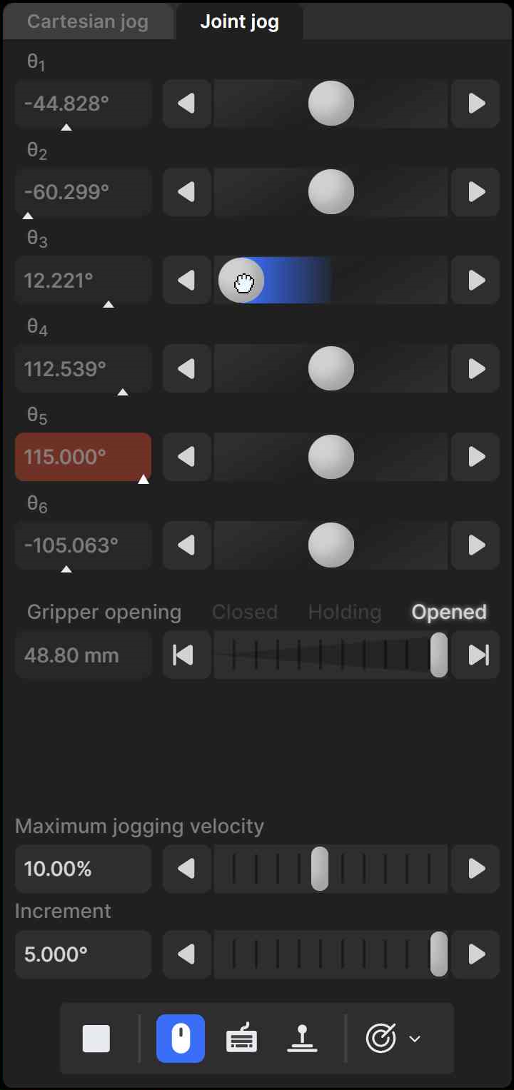
We use an innovative UI element for jogging each joint. That jogging bar is a mixture of a slider and a virtual single-axis joystick and has dual functionality, depending on which mouse button is used to interact with it (Figure 3). You can also jog each joint using keyboard shortcuts, as well as a three-axis or a six-axis joystick with at least two buttons. (Technically, you can use other joysticks, such as a PlayStation controller, but the icons displayed will be those for the SpaceMouse.)
By default, only the mouse is activated, and the button  at the bottom of
the jogging panel is highlighted in blue. To jog each axis as if using a joystick, click
the primary mouse button onto the thumb of the corresponding jogging bar and drag it
right or left (Figure 3a). The further you drag the thumb away
from its central position, right or left, the faster the joint turns, in positive or
negative direction, respectively. In other words, you are directly controlling the joint
speed, rather than the joint position. Alternatively, you can directly click with the
primary mouse button on either of the two arrow buttons of the jogging bar and hold,
which makes the joint rotate at the specified maximum jogging velocity.
at the bottom of
the jogging panel is highlighted in blue. To jog each axis as if using a joystick, click
the primary mouse button onto the thumb of the corresponding jogging bar and drag it
right or left (Figure 3a). The further you drag the thumb away
from its central position, right or left, the faster the joint turns, in positive or
negative direction, respectively. In other words, you are directly controlling the joint
speed, rather than the joint position. Alternatively, you can directly click with the
primary mouse button on either of the two arrow buttons of the jogging bar and hold,
which makes the joint rotate at the specified maximum jogging velocity.
 (a)
(a)
 (b)
(b)
 (c)
(c)
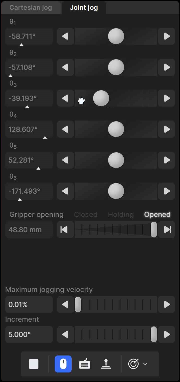
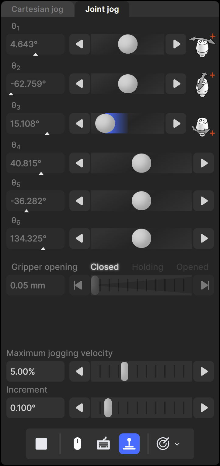
Figure 3 Joint jog tab when using (a) the primary mouse button, (b) the secondary mouse button, and (c) a 3‑axis joystick#
You can also drag the thumbs of the jogging bars using the secondary mouse button (Figure 3b). Doing so, it is the mouse horizontal velocity (rather than relative position) that is mapped to the robot joint velocity. Additionally, clicking the left or right arrow buttons with the secondary mouse button commands a single incremental joint displacement, with the increment specified in the specified in the text field at the bottom of the jogging panel.
You can also directly specify the joint value by entering the joint angle in the text field next to each jogging bar. Note that each text field changes to yellow when the joint position is close to one of its limits or to a singularity (joints 3 and 5 only), or to red, when the joint position is at a limit or at a singularity, as is the case with the robot position display in the 3D view panel. In addition, the little triangle underneath each bar indicates the relative joint position with respect to the joint limits.
You can use keyboard shortcuts to jog the robot by activating the toggle button
 . Table 4 the default keyboard shortcuts for
jogging the robot. The shortcuts are active only if the toggle button is
selected and the mouse cursor is over the jogging panel, in which case the panel is
surrounded by a blue frame. You can change most of these shortcuts in the configuration
menu,
. Table 4 the default keyboard shortcuts for
jogging the robot. The shortcuts are active only if the toggle button is
selected and the mouse cursor is over the jogging panel, in which case the panel is
surrounded by a blue frame. You can change most of these shortcuts in the configuration
menu,  .
.
Shortcut |
Action |
|---|---|
Shift+q [1] or q |
Rotate joint 1 or move end-effector along x-axis, in negative direction |
Shift+w or w |
Rotate joint 1 or move end-effector along x-axis, in positive direction |
Shift+a or a |
Rotate joint 2 or move end-effector along y-axis, in negative direction |
Shift+s or s |
Rotate joint 2 or move end-effector along y-axis, in positive direction |
Shift+z or z |
Rotate joint 3 or move end-effector along z-axis, in negative direction |
Shift+x or x |
Rotate joint 3 or move end-effector along z-axis, in positive direction |
Shift+e or e |
Rotate joint 4 or rotate end-effector about x-axis, in negative direction |
Shift+r or r |
Rotate joint 4 or rotate end-effector about x-axis, in positive direction |
Shift+d or d |
Rotate joint 5 or rotate end-effector about y-axis, in negative direction |
Shift+f or f |
Rotate joint 5 or rotate end-effector about y-axis, in positive direction |
Shift+c or c |
Rotate joint 6 or rotate end-effector about z-axis, in negative direction |
Shift+v or v |
Rotate joint 6 or rotate end-effector about z-axis, in positive direction |
Shift+arrow or arrow |
Jog along each of the four directions chosen in the jogging pad |
1 |
Open Cartesian jog panel and select TRF mode |
2 |
Open Cartesian jog panel and select WRF mode |
3 |
Open joint jog panel |
. |
Toggle between TRF and WRF mode, if Cartesian jog panel open |
- |
Reduce jog velocity |
= |
Increase jog velocity |
Finally, you can jog the robot using either a 3-axis USB precision joystick
(Figure 4a) or the SpaceMouse® 6-axis joystick from 3Dconnexion
(Figure 4b). To use a 3-axis or a 6-axis joystick, you need to activate
the button  . For the MecaPortal to detect the joystick, you will need to
press one of the device’s buttons or, occasionally, unplug and replug the device. Once
the joystick is detected you will see the respective joystick icons next to each slider
(Figure 3c).
. For the MecaPortal to detect the joystick, you will need to
press one of the device’s buttons or, occasionally, unplug and replug the device. Once
the joystick is detected you will see the respective joystick icons next to each slider
(Figure 3c).
Danger
Contrary to the keyboard shortcuts for jogging the robot, the joystick is active even if the mouse cursor is not over the jogging menu, as long as the focus is on the MecaPortal.
Danger
Having multiple input modes for jogging activated simultaneously is unsafe. You should enable only one input mode at a time: the mouse, keyboard shortcuts, or the joystick.
Note
Do not install the driver and the software that come with the SpaceMouse as these will interfere with the desired functioning of the device in the MecaPortal. Also, if you opt for the wireless model, keep the device close to the universal USB receiver and remember to recharge the device regularly.
You can deactivate certain joystick directions by clicking on the respective joystick
icon, to the right of each slider bar. You can even customize the mapping between the
joystick “axes” and the jogging directions in the configuration menu, .
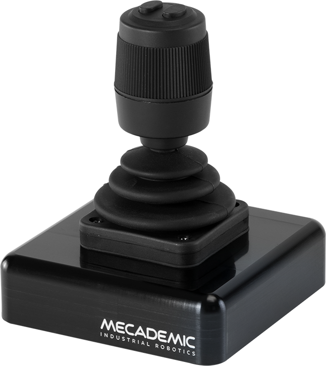 (a) an example of a 3-axis USB precision joystick
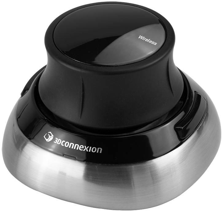 (b) SpaceMouse® 6-axis joystick from 3Dconnexion
Figure 4 USB joysticks that can be used with the MecaPortal#
To select between joint jog, Cartesian jog with respect to the TRF or Cartesian jog with respect to the WRF, you can either use your mouse or press (up to two times if necessary) the right button of the SpaceMouse or of the 3-axis joystick until the desired selection is obtained.
For much more precise jogging, we strongly recommend the use of a 3-axis precision USB joystick such as from APEM.
In both the joint jog and Cartesian jog panels, there are sliders with text-fields for controlling your MEGP 25* gripper, the maximum jogging velocity, and the increment (for incremental jogging). You can also use the keyboard shortcut Alt+G to open/close the MEGP 25* gripper.
Finally, for convenience, the same stop button  available at the bottom
of the code editor is also provided at the bottom of both jogging menus. Lastly, a list
of predefined robot positions (essentially, joint sets) are stored and available in the
available at the bottom
of the code editor is also provided at the bottom of both jogging menus. Lastly, a list
of predefined robot positions (essentially, joint sets) are stored and available in the
 menu button. Clicking on one of these robot positions moves the robot to
that joint set, in joint mode.
menu button. Clicking on one of these robot positions moves the robot to
that joint set, in joint mode.
7.2. The Cartesian jog tab#
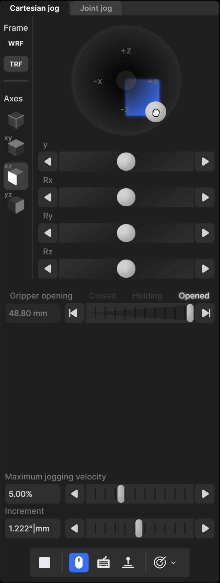
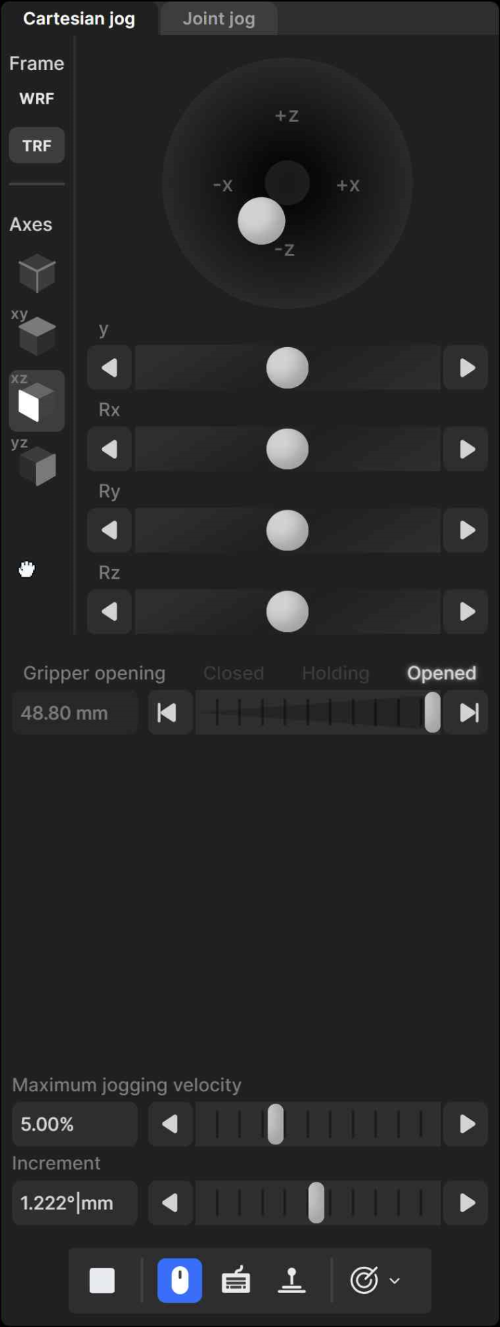
In the Cartesian jog tab (Figure 5), you can move the robot along (labels X, Y, Z) or about (labels Rx, Ry, or Rz) the axes of the TRF (if the TRF button is selected, as in the figure) or along or about the axes of a reference frame having the same orientation as the WRF but with origin at the TCP (if WRF is selected). As with the joint jog tab, the jogging bars can be controlled with both the primary (Figure 5a) and secondary (Figure 5b) mouse buttons, using the same logic. However, you can merge two jogging bars for linear movement (i.e., X and Y, Y and Z, or Z and X) into a 2D jogging pad using the buttons under the label “Axes”. Note that subsequent clicks on one of these buttons changes the jogging directions in the 2D jogging pad (there are a total of eight combinations).
 (a)
(a)
 (b)
(b)
 (c)
(c)
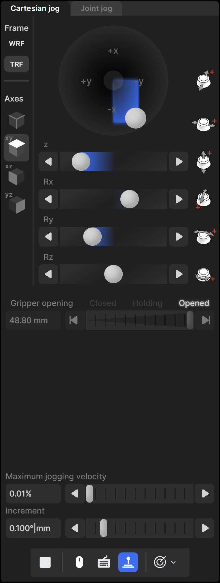
Figure 5 Cartesian jog tab when using (a) the primary mouse button, (b) the secondary mouse button, and (c) the SpaceMouse#
The other major difference is that there are no text fields showing the position and orientation of the TRF with respect to the WRF, next to each jogging bar, let alone visual cues for indicating whether Cartesian jogging in one direction might soon reach a workspace limit. This is mainly because, in general, jogging along and about the three axes of a reference frame have no one-to-one correlation to the position coordinates and Euler angles used to represent the pose of the TRF with respect to the WRF. Furthermore, other than mechanical interferences between non-adjacent links of the robot, the factors that limit the robot workspace are the joints limits and the singularities, which are already displayed in the robot position display, in the top right corner of the MecaPortal.
The keyboard shortcuts for Cartesian jogging are shown in Table 4.
Finally, you can jog in Cartesian mode using a joystick. Figure 5c shows the Cartesian jog tab in the case of the SpaceMouse.
Danger
Having multiple input modes for jogging activated simultaneously is unsafe. You should enable only one input mode at a time: the mouse, keyboard shortcuts, or the joystick.
Note
In Cartesian jog, when reorienting the end-effector using the Rx, Ry and Rz arrow buttons, you do not modify independently each Euler angle, but rather rotate the TRF about axes passing through its origin (the TCP) and coincident with its x, y or z axes, if the TRF option is chosen, or parallel to the x, y or z axes of the WRF, if the WRF option is chosen.