3. Installing the module#
The MVK01 module is designed for only one type of installation, underneath the base of the MCS500 R1, as shown in Figure 6.
Warning
Make sure the MCS500 robot is powered off and the connectors on top of the MVK01 and on the bottom of the robot’s base are unobstructed, before installing the MVK01 module.
 (a)
(a)
 (b)
(b)
Figure 6 Installing the MVK01 module underneath the base of the MCS500 R1#
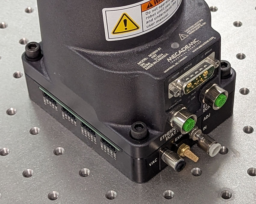
The electric connection between the MCS500 robot and the MVK01 module is made through the seven spring-loaded connectors on top of the MVK01. Make sure there’s nothing that obstructs that connection, before installing the MVK01 module. Then make sure the MCS500 robot is switched off and the arm fully folded and follow these steps:
Align the two diagonally opposed centering sleeves (hollow Dowel pins) with the corresponding locating holes at the bottom of the robot base, and then gently slide down the MCS500 until there is no gap between the top of the MVK01 module and the bottom of the robot’s base (Figure 6a).
Carefully align the new assembly with the four M6 threaded holes for mounting the MCS500 and attach the assembly with four M6 screws of length 45 mm or more (Figure 6b). Tighten the screws with a torque of 8 Nm.
Warning
Until the base of the MCS500 is fixed with at least two M6 screws, keep the arm fully folded and always hold the robot with one hand to prevent the robot from tipping over.
Note that the MVK01 is precision machined and you can use locating pins to constrain the module, and therefore the complete robot-module assembly, in the same way as you would constrain the base of the MCS500. You can use 2+1 locating pins touching two adjacent sides of the module, as we do in our MUAP02 adaptor plate (which you can use for the module too).
Next, if you choose to use our optional suction cup holder, install it on the bottom extremity of the robot’s spline shaft or on the top extremity, depending on your application, by following these steps:
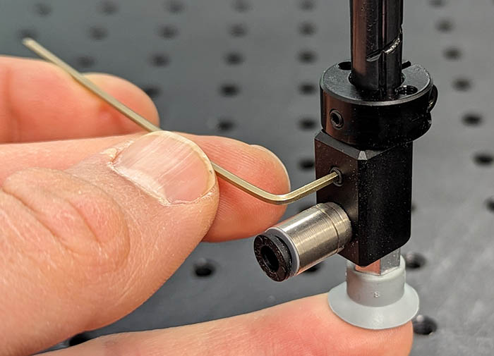
Unscrew (if necessary) the set screw in the adaptor with a 1.5-mm Allen key so that the screw is not protruding into the 8-mm hole.
Slide the suction cup holder’s 8-mm hole onto the extremity of the robot’s spline shaft until it makes contact with the black retaining ring on the spline shaft.
Reorient the adaptor while pushing it against the retaining ring, until the set screw on top of the push-in connector aligns with the set screw of the retaining ring. It is extremely important to make sure that the set screw on the suction cup holder is perpendicular to the Weldon flat surface, or else you will damage the spline shaft of the robot in step 4.
Screw in the set screw of the suction cup holder and tightened it using a torque of 1.5 Nm (Figure 7a).
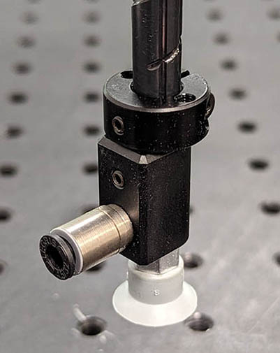
Screw the desired suction cup into the M5 threaded hole of the suction cup holder (this step can be done in advance, Figure 7b).
 (a) Installing the suction cup holder
 (b) Suction cup fully installed
Figure 7 Installing the optional suction cup holder (MCS500-TA01)#
Warning
Do not remove the retaining rings from the spline shaft, as doing so will cause irreversible damage to the ball-screw spline assembly.
Figure 8 shows the main dimensions of the optional suction cup holder. You can also download the CAD file of the holder from here.


Figure 8 Main dimensions of the optional suction cup holder#
Finally, insert 6-mm (OD) pneumatic tubing providing the compressed air (7 bar) into the push-in connector of the IN port on the MVK01 module. Then, cut the proper length of pneumatic tubing with 4-mm outer diameter and connect one end to the VAC port on the MVK01 module and the other to the push-in connector of the suction cup holder. Attach the tubing with a tie wrap to the rigid cable conduit of the SCARA robot as shown in Figure 9. Make sure the tubing is sufficiently long for the active joint ranges of the robot, specified by the command SetJointLimits.
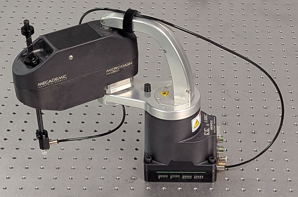
Figure 9 Complete installation of the MVK01 and the optional cup holder#