4. Pneumatic circuit examples#
As already specified, the MPM500 consists of two three-way, two-position normally closed valves that can be controlled independently. The valves share the same inlet port (IN) and exhaust port (OUT). The following two sections present three typical examples of pneumatic circuits.
Note
If you operate the valves in a continuous manner, the module may heat up. This is normal.
4.1. Double-action pneumatic gripper#
To connect your MPM500 to a double-action pneumatic gripper, as in Figure 4, follow the circuit of Figure 5 The compressed air should be introduced in the MPM500’s IN port. It will be distributed to both 3/2 NC valves. The solenoid switch activates one valve which allows for the gripper to open/close its fingers, depending on which valve is activated. The gripper’s pneumatic connectors should go in the MPM500’s Port 1 and Port 2.
You should use the same pneumatic circuit in the case of a tool changer.
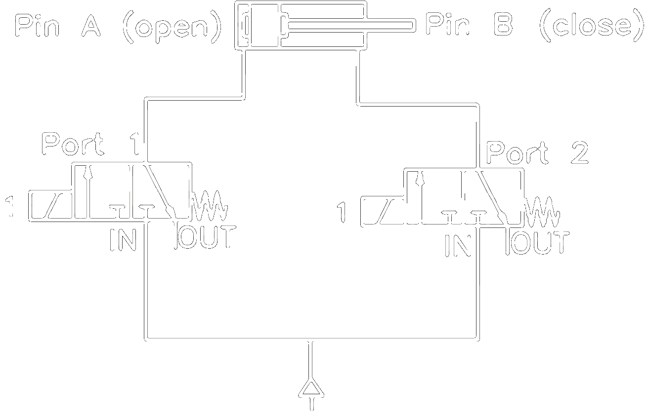
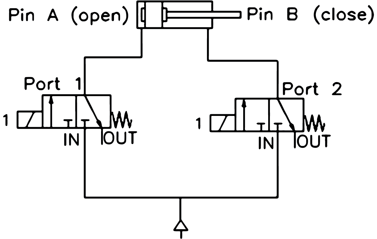
Figure 5 Pneumatic circuit in the case of a double-action pneumatic gripper#
4.2. Vacuum suction cup#
To connect the MPM500 to vacuum suction cups, follow the circuits on Figure 6 or Figure 7. In each of these two cases, only one of the valves is used.
With the first circuit (Figure 6), the compressed air must enter the MPM500’s IN port. When the valve is activated the air flows towards a venturi vacuum pump and connects to its positive pressure port. The suction cup, and an additional air filter if necessary, are connected to the venturi vacuum pump’s negative pressure port. The vacuum is toggled with the activation (open state) and release (close state) of the valve. If you have a compact venturi vacuum generator, this circuit is the most efficient one.
A more practical way to connect a suction cup, especially if your vacuum generator is bulky, is presented on Figure 7. The compressed air is sent directly to the venturi pump on its positive pressure port.
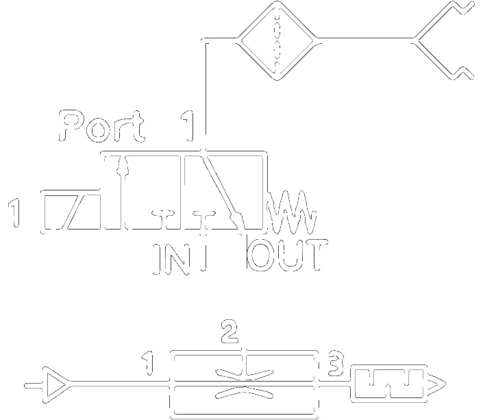
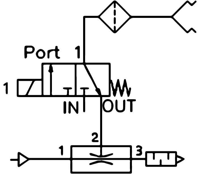
Figure 6 Pneumatic circuit in the case of a suction cup and a small venturi vacuum generator#
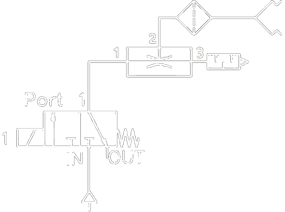
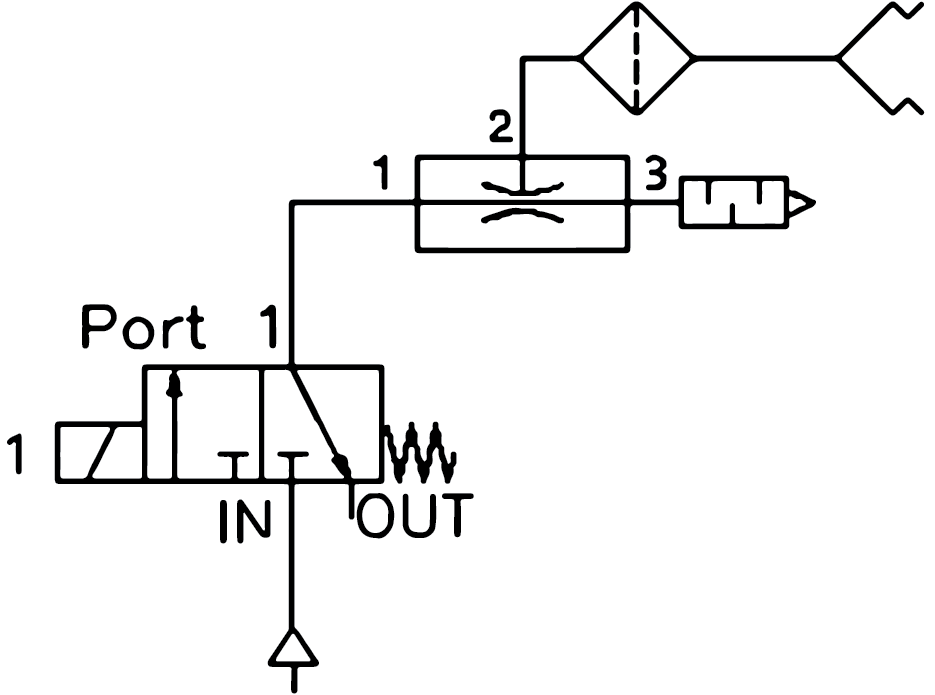
Figure 7 Pneumatic circuit in the case of a suction cup and a bulkier venturi vacuum generator#
This circuit should also be used when working with a direct vacuum line. The vacuum line is connected to the OUT port of the MPM500, while the end-of-arm tooling is connected either to Port 1 or Port 2 of the pneumatic module.
Note
If you are using a vacuum line instead of a compressed air line, make sure to connect it to the OUT port of the MPM500, as shown in Figure 7.