4. Installing the gripper#
The communication cables that come with the MEGP 25* grippers are designed for only two types of installation: using the standard adapter plate or the optional 90° adapter plate. If mounting the gripper on the Meca500 flange differently, you must design and machine your own adapter plate.
4.1. Installation steps#
Before installing the gripper, the robot must be setup properly:
Turn the robot on.
Open the MecaPortal web interface and activate and home the robot.
Bring all joints to zero degrees.
Once all joints are zeroed, switch the robot off before proceeding to install the gripper.
Warning
The robot must be powered off before proceeding to install the gripper. The fingers must already be installed on the gripper.


Figure 5 Installing the MEGP 25E gripper (fingers are not shown)#
Install the gripper following the installation steps below, as shown in Figure 5
Make sure the flange of the robot is in zero position (screw in the flange is at 12 o’clock).
Attach the adapter plate using the four M3X0.5X8 Torx flat head screws provided. Make sure to install the plate in the proper orientation, as shown in Figure 6


Figure 6 Proper adapter plate orientation (when all joints are at zero degrees, arrows should point towards the robot base)#
Warning
Use only the screws provided; longer screws will damage joint 6.
Attach the gripper to the adapter plate using the two M2.5X0.45 socket head screws provided.
Attach the appropriate end of the cable to the gripper.
Remove the screw cap from the tool I/O port on the robot (keep for future use). Attach the other end of the cable to the port.
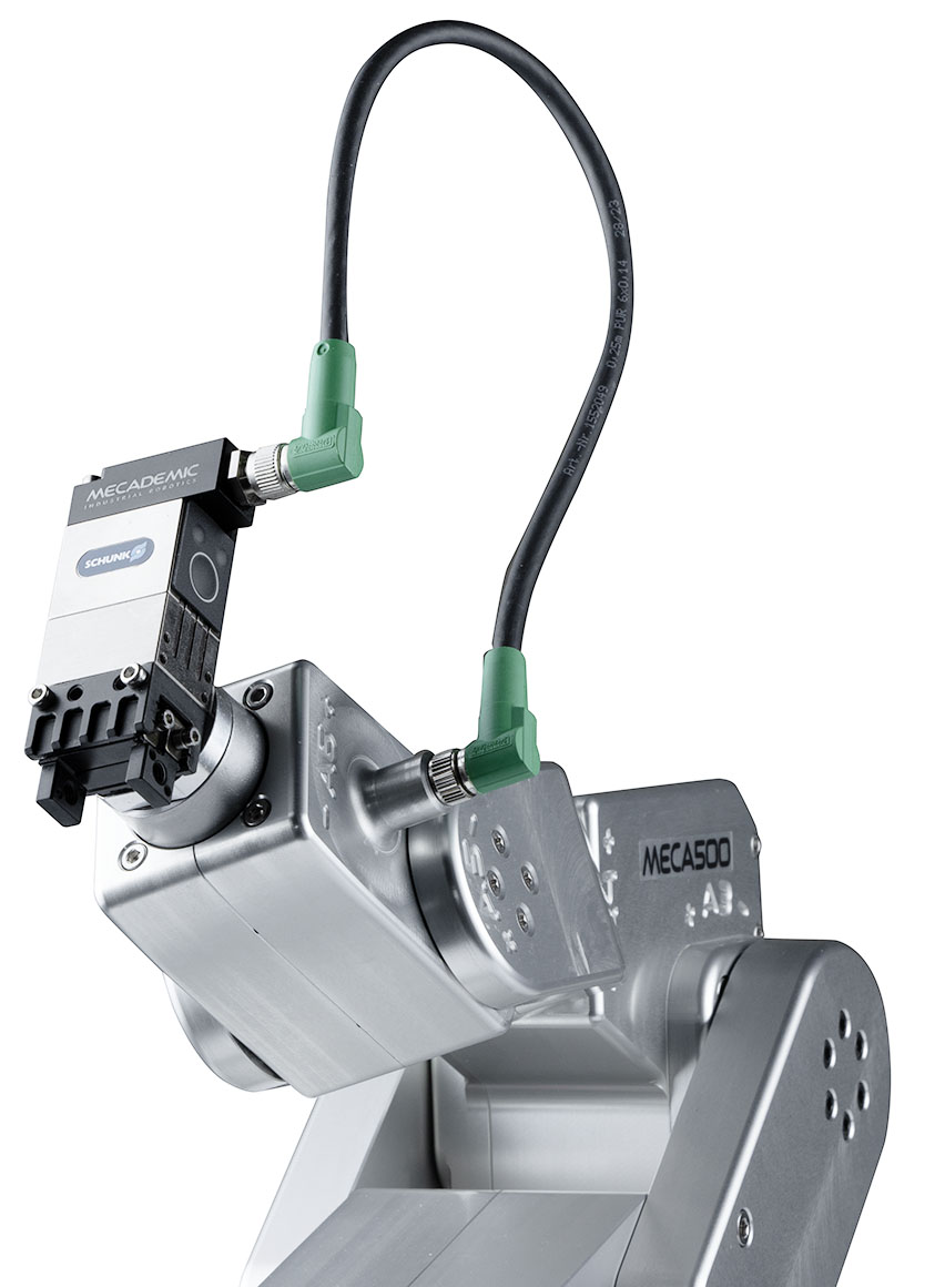
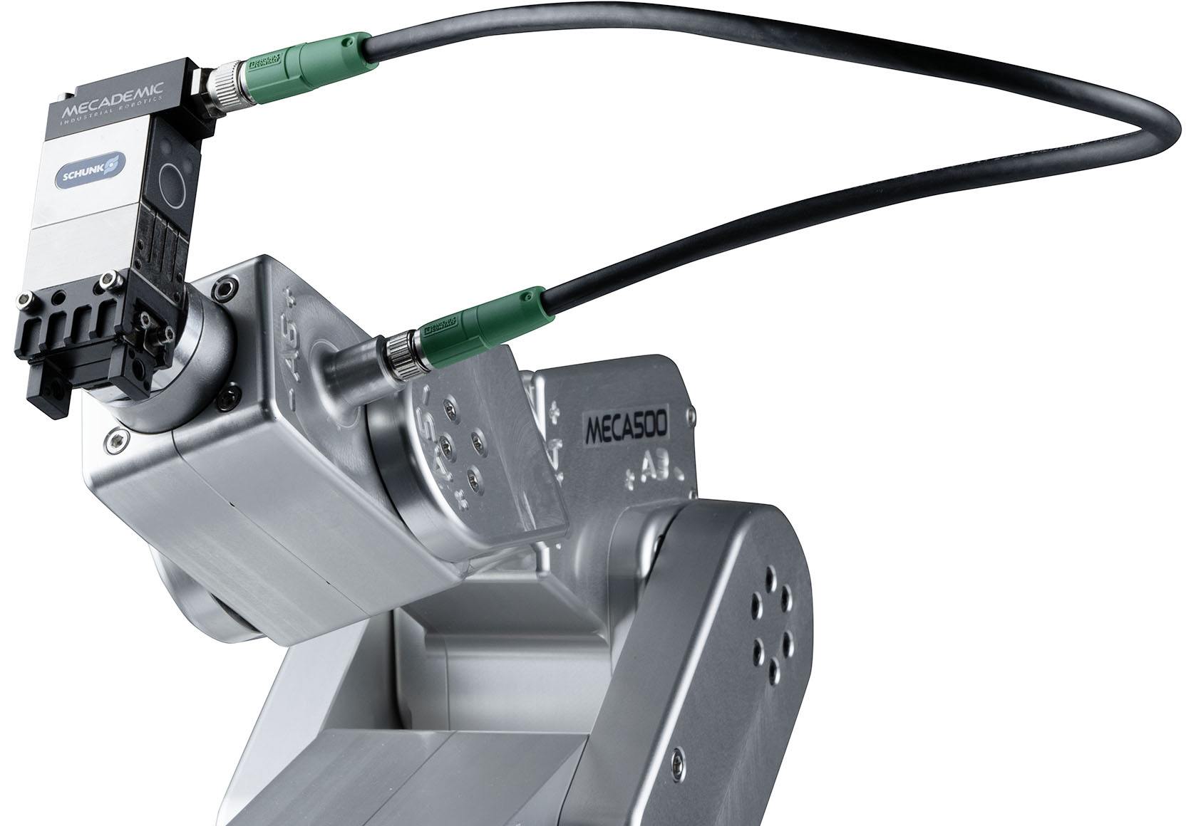
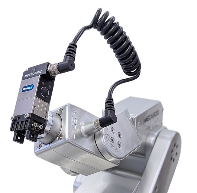
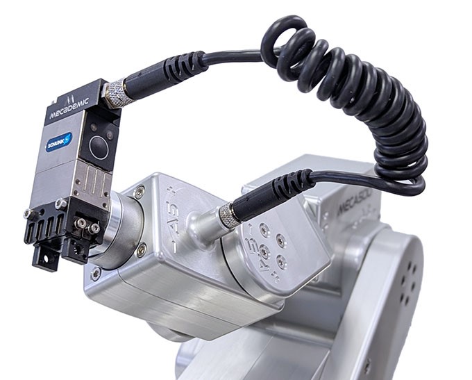
Figure 7 shows the MEGP 25 gripper installed, in the case of all four types of cables.
 (a) MGC-AA25 (discontinued)
 (b) MGC-SS35 (discontinued)
 (c) MGC-HFA
 (d) MGC-HFC
Figure 7 MEGP 25E gripper installed with the four different cables (fingers not shown)#
Once the gripper is installed, you can start using the robot. When the Meca500 is activated, it will automatically detect the gripper, and the green LED on the gripper will flash slowly.
The gripper is automatically homed when the robot is homed; it will fully open then close its fingers. This homing procedure is necessary to detect the range of motion of the fingers (in case their design reduces the nominal 6-mm range, for the MEGP 25E, or 48-mm range, for the MEGP 25LS). Once the gripper is homed, the green LED on the gripper will light up continuously.
Now that you have installed and homed your gripper, you must carefully test and then
redefine the range of joint 6 with the command SetJointLimits in order to make sure that
the gripper cable does not cause interferences. In the case of the standard adapter
plate described in this section and the optional 90° adapter plate, the recommended
maximal range for joint 6 is [−180°, 180°].
Warning
Once you have installed your MEGP 25* gripper you must redefine the range of joint 6
using the command SetJointLimits, or else you risk to damage the gripper and its
cable.
4.2. Gripper LEDs#
There are two LEDs on the gripper, just below the tool I/O port: one green and one red. Their behavior indicates the gripper status as described in the table below.
LED |
Steady ON |
Slow Blink |
Fast Blink |
|---|---|---|---|
RED |
Holding part |
Error |
n/a |
GREEN |
Homed |
Activated but not homed |
Connected but not activated |
Note
The button located below the gripper LEDs is inactive and provides no functionality.